508155-01Issue 2108Page 2 of 49
Technical Specications - A80US2V
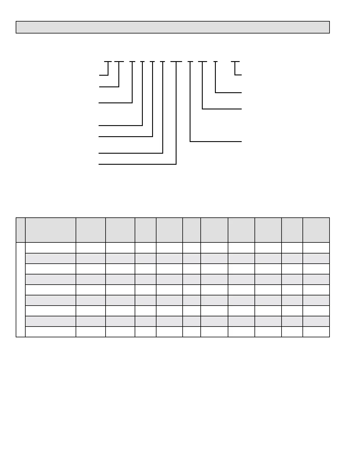
MODEL NUMBER GUIDE
PHYSICAL AND ELECTRICAL DATA
Model
Input
(Btuh)
Output*
(Btuh)
AFUE
(ICS)
Nominal
Cooling
Capacity
Gas
Inlet
(in.)
Volts/
Hz/
Phase
Max. Time
Delay
Breaker or
Fuse
Nominal
F.L.A.
Trans.
(V.A.)
Approx.
Shipping
Weight
(lbs.)
UPFLOW/HORIZONTAL
A80US2V070A12 66,000 52,000 80.0% 3 tons 1/2 120-60-1 15 7.7 40 128
A80US2V090B12 88,000 70,000 80.0% 3 tons 1/2 120-60-1 15 7.7 40 143
A80US2V090B16 88,000 70,000 80.0% 4 tons 1/2 120-60-1 20 12.8 40 154
A80US2V090C20 88,000 70,000 80.0% 5 tons 1/2 120-60-1 20 12.8 40 173
A80US2V110C20 110,000 87,000 80.0% 5 tons 1/2 120-60-1 20 12.8 40 181
A80US2V135D20 132,000 105,000 80.0% 5 tons 1/2 120-60-1 20 12.8 40 199
A80US2V070A12L 66,000 52,000 80.0% 3 tons 1/2 120-60-1 15 7.7 40 128
A80US2V090B16L 88,000 70,000 80.0% 4 tons 1/2 120-60-1 20 12.8 40 154
A80US2V110C20L 110,000 87,000 80.0% 5 tons 1/2 120-60-1 20 12.8 40 181
Note: For vent length and clearances to combustibles, please reference installation instructions.
* Outputs shown are High Fire, 100% rate, Low Fire is 67% of shown output.
Major Revision Code
Numeric Code
Option Code
L = Low NOx
Nom. CFM x 100
8 = 3 Ton add on cooling
12 = 3 Ton add on cooling
16 = 4 Ton add on cooling
20 = 5 Ton add on cooling
Cabinet Width
A = 14.5" WIDTH
B = 17.5” width
C = 21.0” width
D = 24.5” width
A = Flagship
AFUE
80 = 80% Efficency
Configuration
U = Upflow/Horizontal
D = Downflow
S = Communicating
Stages
2 = Two Stage
V = Variable Speed
BTUH Width
Heating Input x 1000
A 80 U S 2 V 110 C 20 L - 01