508155-01Issue 2108Page 40 of 49
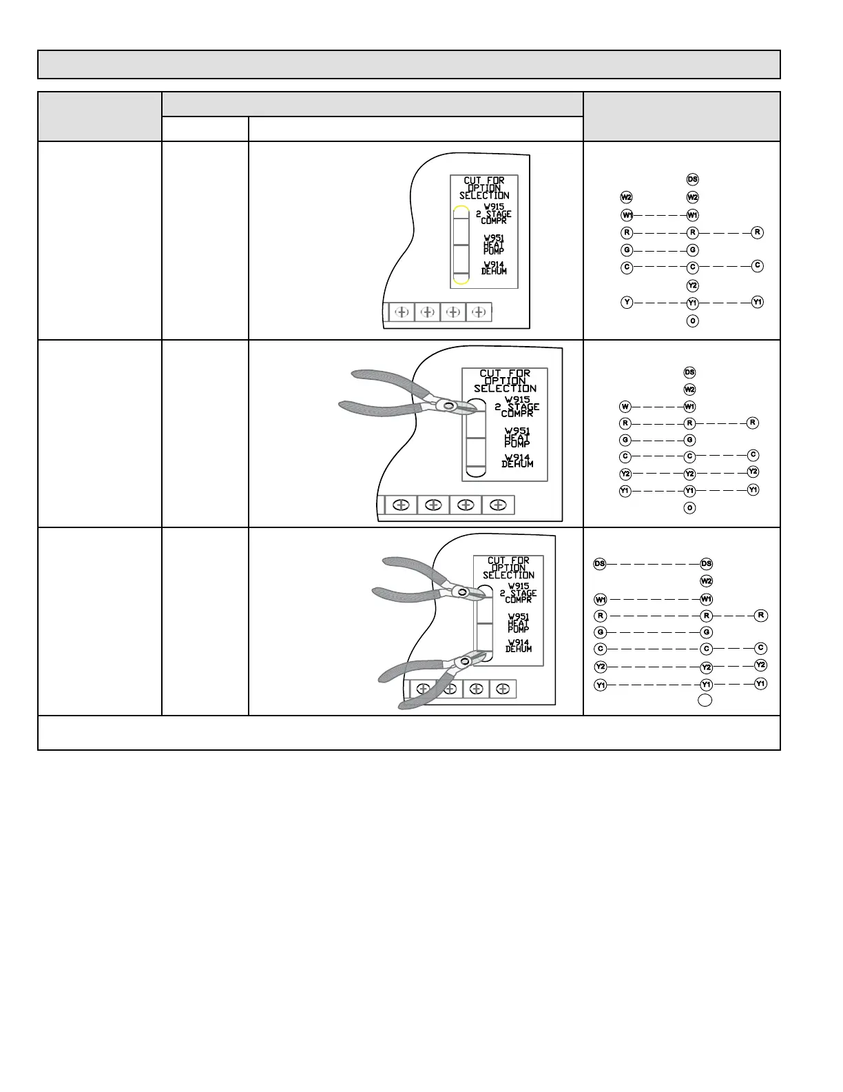
Field Wiring Applications with Conventional Thermostat
Thermostat
DIP Switch Settings and On-Board Links
Wiring Connections
DIP Switch 1 On Board Links Must Be Cut To Select System Options
1 Heat / 1 Cool
NOTE: Use DIP
switch 2 to set
sceond-stage heat
ON delay.
OFF - 7 minutes
ON - 12 minutes
ON
DO NOT CUT ANY
ON-BOARD LINKS
T'STAT
TERM. STRIP
UNIT
*
*Not required on all unit
s
1 Heat / 2 Cool
NOTE: Use DIP
switch 2 to set
sceond-stage heat
ON delay.
OFF - 7 minutes
ON - 12 minutes
ON
CUT ON-BOARD LINK
W915
2 STAGE
COMPR
T'STAT
TERM. STRIP
UNIT
*
*Not required on all unit
s
1 Heat / 2 Cool
with t’stat with
dehumidication
mode
NOTE: Use DIP
switch 2 to set
sceond-stage heat
ON delay.
OFF - 7 minutes
ON - 12 minutes
ON
CUT ON-BOARD LINK
W915
2 STAGE
COMPR
CUT ON-BOARD LINK
W914
DEHUM
TERM. STRIP
UNIT
*
*Not required on all units
NOTE - Do NOT make a wire connection between the room thermostat L terminal and the L terminal of the A80US2V integrated
control.
Table 21. Field Wiring for Non-Communicating Thermostat Applications