508155-01 Issue 2108 Page 31 of 49
Typical Operating Characteristics
Blower Operation and Adjustment
1. Blower operation is dependent on thermostat control
system.
2. Generally, blower operation is set at thermostat
subbase fan switch. With fan switch in ON position,
blower operates continuously. With fan switch in
AUTO position, blower cycles with demand or runs
continuously while heating or cooling circuit cycles.
3. Depending on the type of indoor thermostat, blower
and entire unit will be o when the system switch is in
OFF position.
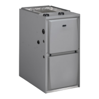
Temperature Rise
Temperature rise for A80US2V units depends on unit input,
blower speed, blower horsepower and static pressure as
marked on the unit rating plate. The blower speed must be
set for unit operation within the range of “TEMP. RISE °F”
listed on the unit rating plate.
Supply Air
Return Air
TEMPERATURE RISE
Supply Duct Temperature ________
Return Duct Temperature
_
_____
Temperature Rise = ________
Figure 19. Temperature Rise
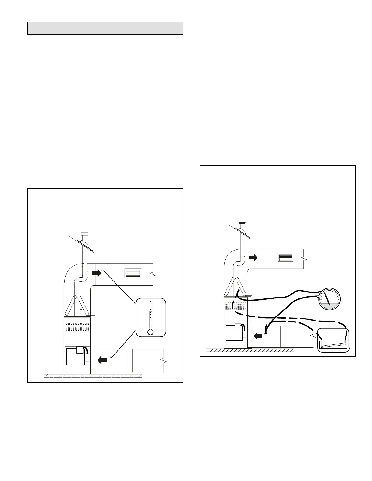
External Static Pressure
1. Tap locations shown in Figure 20.
2. Punch a 1/4” diameter hole in supply and return air
plenums. Insert manometer hose ush with inside
edge of hole or insulation. Seal around the hose with
permagum. Connect the zero end of the manometer to
the discharge (supply) side of the system. On ducted
systems, connect the other end of manometer to the
return duct as above.
3. With only the blower motor running and the evaporator
coil dry, observe the manometer reading. Adjust blower
motor speed to deliver the air desired according to the
job requirements. For heating speed (second-stage
heat speed) external static pressure drop must not be
more than 0.8” W.C. For cooling speed (second-stage
cool speed) external static pressure drop must not be
more than 1.0” W.C.
4. Seal the hole when the check is complete.
EXTERNAL STATIC PRESSURE
Supply Duct Static ________
Return Duct Static + _____
Total Duct Static =
________
(dry coil)
Supply Air
Return Air
or
Figure 20. Static Pressure Test