507276-03Page 34 of 59 Issue 1621
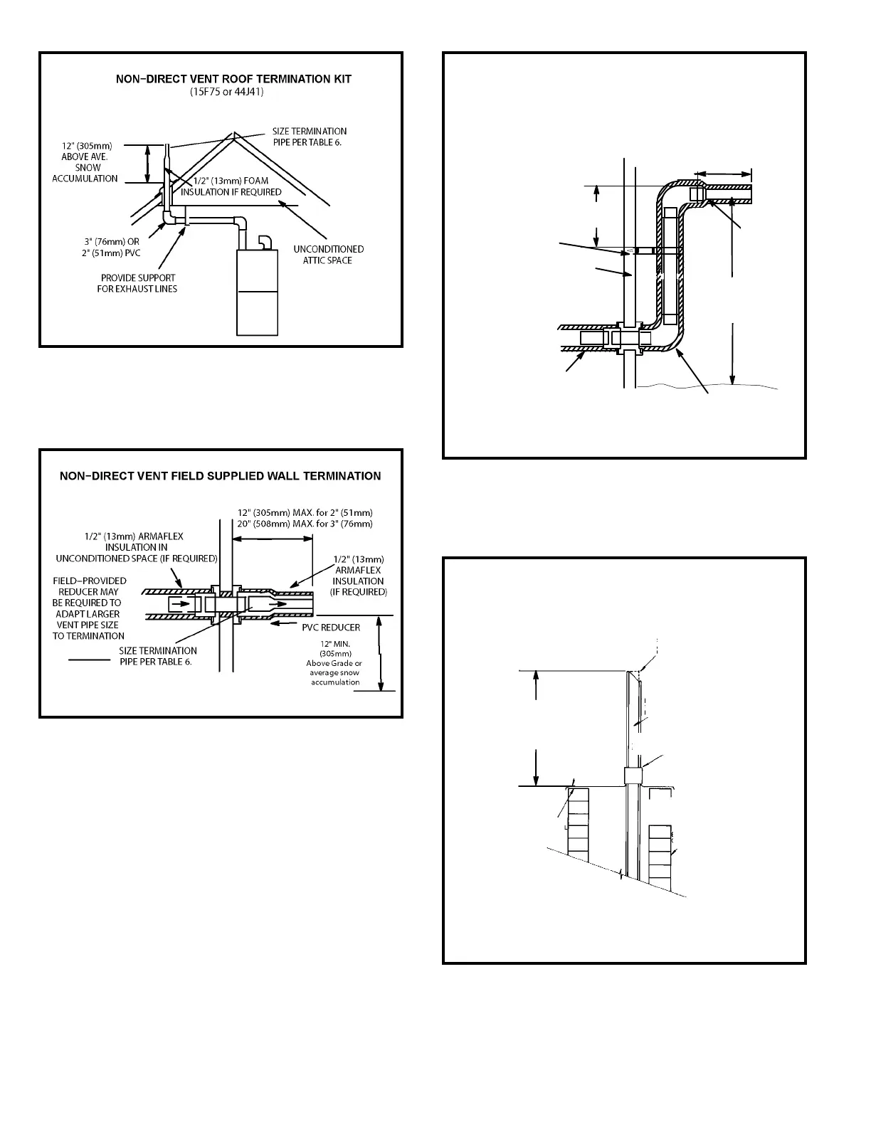
3. If exhaust piping must be run up a sidewall to position
above snow accumulation or other obstructions, piping
must be supported every 24” (610 mm) as shown in
Figure 48. When exhaust piping must be run up an
outside wall, any reduction in exhaust pipe size must
be done after the nal elbow.
Figure 47
Figure 46
Figure 48
12" (305mm)
ABOVE GRADE OR
AVERAGE SNOW
ACCUMULATION
UNCONDITIONED
SPACE
1/2" (13mm) FOAM
INSULATION (IF REQUIRED)
1/2" (13mm) FOAM
INSULATION IN
UNCONDITIONED
SPACE (IF REQUIRED)
*WALL SUPPORT
OUTSIDE WALL
SIZE TER-
MINATION
PIPE PER
TABLE 8.
FIELD−PROVIDED
REDUCER MAY BE
REQUIRED TO
ADAPT LARGER
VENT PIPE SIZE TO
TERMINATION
*Use wall support every 24" (610). Use two supports if extension is
greater than 24" but less than 48".
12" (305mm) MAX. for 2" (51mm)
20" (508mm) MAX. for 3" (76mm)
6" (152mm)
Max
Non-Direct Vent Field Supplied Wall
Termination Extended
Figure 49
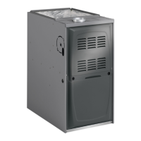
NOTE − Do not discharge exhaust gases directly into any chimney or vent st ack. If ver-
tical discharge through an existing unused chimney or stack is required, insert piping
inside chimney until the pipe open end is above top of chimney and terminate as illus-
trated. In any exterior portion of chimney, the exhaust vent must be insulated.
STRAIGHT−CUT OR
ANGLE−CUT IN DIRECTION
OF ROOF SLOPE
EXHAUST VENT
1/2" (13mm)
WEATHERPROOF
INSULATION (IF REQUIRED)
SHOULDER OF FITTINGS
PROVIDE SUPPORT
OF PIPE ON TOP PLATE
EXTERIOR
PORTION OF
CHIMNEY
INSULATE
TO FORM
SEAL
SHEET
METAL TOP
PLATE
SIZE TERMINATION
PIPE PER TABLE 8.
Minimum 12" (305mm)
above chimney top
plate or average snow
accumulation
Non-Direct Vent Application
Using Existing Chimney