507404-02 Page 17 of 80Issue 1448
3. Close all building doors and windows and all doors
between the space in which the appliances remaining
connected to the common venting system are located
and other spaces of the building. Turn on clothes dryers
and any appliances not connected to the common
venting system. Turn on any exhaust fans, such as
range hoods and bathroom exhausts, so they will
operate at maximum speed. Do not operate a summer
exhaust fan. Close replace dampers.
4. Follow the lighting instructions. Turn on the appliance
that is being inspected. Adjust the thermostat so that
the appliance operates continuously.
5. After the main burner has operated for 5 minutes, test
for leaks of ue gases at the draft hood relief opening.
Use the ame of a match or candle.
6. After determining that each appliance connected to
the common venting system is venting properly, (step
3) return all doors, widows, exhaust fans, replace
dampers, and any other gas burning appliances to their
previous mode of operation.
7. If a venting problem is found during any of the preceding
tests, the common venting system must be modied to
correct the problem.
Resize the common venting system to the minimum vent
pipe size determined by using the appropriate tables in
Appendix G. (These are in the current standards of the
National Fuel Gas Code ANSI Z223.1.)
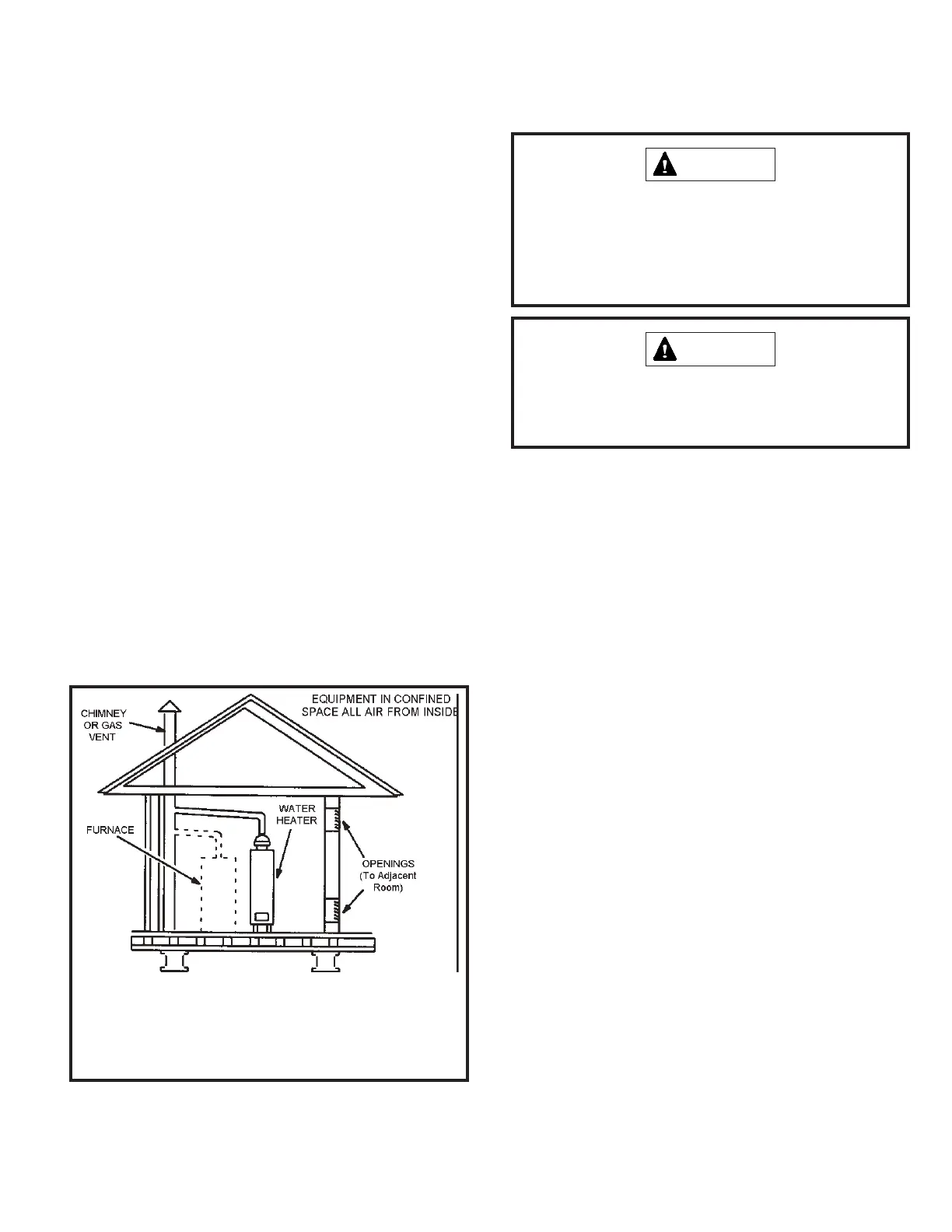
Figure 21
If this gas furnace replaces a furnace which was commonly vented with
another gas appliance, the size of the existing vent pipe for that gas
appliance must be checked. Without the heat of the original furnace
ue products, the existing vent pipe is probably oversized for the single
water heater or other appliance. The vent should be checked for proper
draw with the remaining appliance.
The exhaust vent pipe operates under positive pressure
and must be completely sealed to prevent leakage of
combustion products into the living space.
CAUTION
Exhaust Piping
Route piping to outside of structure. Continue with
installation following instructions given in piping termination
section.
Do Not discharge exhaust into an existing stack or
stack that also serves another gas appliance. If vertical
discharge through an existing unused stack is required,
insert PVC pipe inside the stack until the end is even
with the top or outlet end of the metal stack.
CAUTION
Vent Piping Guidelines
This gas furnace can be installed as either Non-Direct
Vent or a Direct Vent gas central furnace.
NOTE: In Non-Direct Vent installations, combustion air is
taken from indoors and ue gases are discharged outdoors.
Intake and exhaust pipe sizing - Size pipe according to
Tables 4 and 5. Table 4 lists the minimum vent pipe
lengths permitted. Table 5 lists the maximum pipe lengths
permitted.
Regardless of the diameter of pipe used, the standard roof
and wall terminations described in section Exhaust Piping
Terminations should be used. Exhaust vent termination
pipe is sized to optimize the velocity of the exhaust gas as
it exits the termination. Refer to Table 7.
In some applications which permit the use of several different
sizes of vent pipe, a combination vent pipe may be used.
Contact Allied Air Technical Service for assistance in sizing
vent pipe in these applications.
NOTE: The exhaust collar on all models is sized to
accommodate 2” Schedule 40 vent pipe. When vent pipe
which is larger than 2” must be used in an upow application,
a transition must be applied at the exhaust collar in order
to properly step to the larger diameter vent pipe. Contact
Allied Air Technical Service for more information concerning
sizing of vent systems which include multiple pipe sizes.