507404-02Page 30 of 80 Issue 1448
NOTE: Care must be taken to avoid recirculation of exhaust
back into intake pipe.
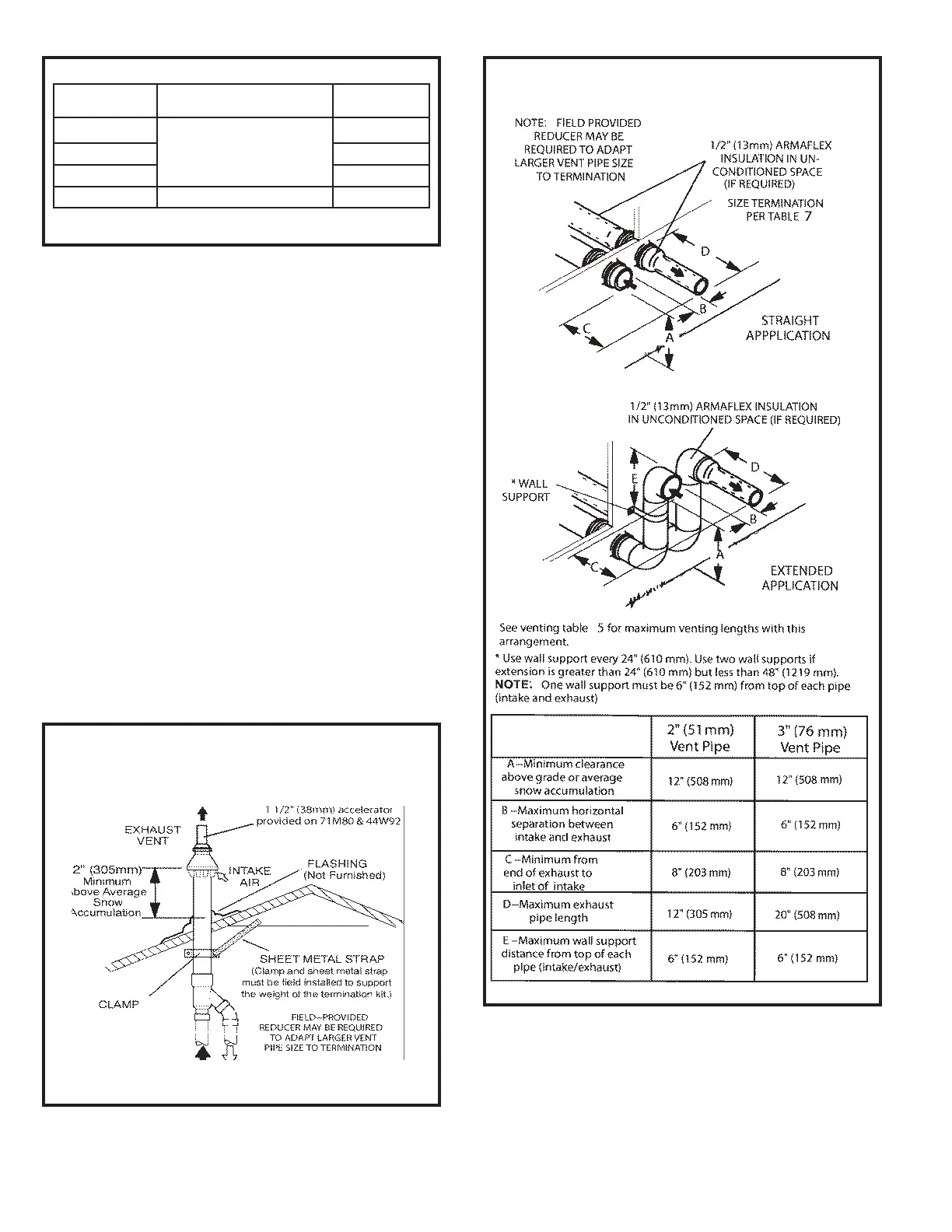
5. On eld supplied terminations for sidewall exit, exhaust
piping may extend a maximum of 12 inches (305 mm)
for 2” PVC and 20 inches (508 mm) for 3” (76 mm) PVC
beyond the outside wall. Intake piping should be as
short as possible. See Figures 37 and 39.
6. On eld supplied terminations, a minimum distance
between the end of the exhaust pipe and the end of
the intake pipe without a termination elbow is 8” and a
minimum distance of 6” with a termination elbow. See
Figure 37.
7. If intake and exhaust piping must be run up a side wall to
position above snow accumulation or other obstructions,
piping must be supported every 24” (610 mm) as shown
in Figures 37. When exhaust and intake piping must be
run up an with pipe sized per Table 6. The intake piping
may be equipped with a 90° elbow turndown. Using
turndown will add 5 feet (1.5 m) to the equivalent length
of the pipe.
8. A multiple furnace installation may use a group of up to
four terminations assembled together horizontally, as
shown in Figure 43.
DIRECT VENT CONCENTRIC ROOFTOP TERMINATION
71M80, 69M29 or 60L46 (US)
41W92 or 41W93 (Canada)
Figure 36
EXHAUST PIPE TERMINATION SIZE REDUCTION
Table 7
* Units with the ush mount termination must use the 1-1/2” accelerator supplied
with the kit
Figure 37
FIELD SUPPLIED WALL TERMINATION
MODEL Exhaust Pipe Size
Termination
Pipe Size
045 and 070
2” (51 mm), 2-1/2” (64 mm),
3” (76 mm)
1-1/2” (38 mm)
090 2” (51 mm)
110 2” (51 mm)
135 3” (76 mm) 2” (51 mm)