507404-02 Page 73 of 80Issue 1448
Program Unit Capacity / Size Mode
1) Refer to gures 53 and 54 for eld wiring when using the Comfort Sync thermostat. Refer to tables 12A,
12B, 12C, and 12D for eld wiring for all non-communicating applications.
2) If the furnace is being matched with a non-communicating heat pump, refer to the instructions packaged
with the dual fuel thermostat.
3) See gure 53
4) Refer to tables 12A, 12B, 12C, and 12D
Power-Up – Number displayed represented by integrated control unit size code(furnace model and capacity). If
three horizontal bars are displayed followed by a continuous E203, furnace control does not recognize unit size
code. Congure per the following:
Verify that the furnace is in idle mode; signied by a ashing dot in the corner of the 7 segment LED display.
Press and hold the button next to the display, until a solid “P” appears. Release the button. Note: replacement
control boards may need to be manually congured to validate the furnace unit size code.
e solid “P” starts blinking. Release the button.
Push and hold the button until unit size codes are displayed. See chart below. When the correct unit size code is
displayed, release the button. e selected code will ash for 10 seconds. During that period, press and hold the
button for 5 seconds. e integrated control will store the code in memory and automatically exit and reset. (If
the 10 seconds expire or the button is held for less than 5 seconds, the control will automatically exit and go into
idle mode without storing the unit size code. If this happens, repeat steps to congure the unit size.)
Verify that the selected unit size code is correct and stored in non-volatile memory. To do this, cycle 24v power
to the control. When the board powers up, the 7 segment LED will display the unit size code. If three horizontal
bars are displayed, this indicates that the board does not recognize a unit size code; programming of the board
will need to be repeated.
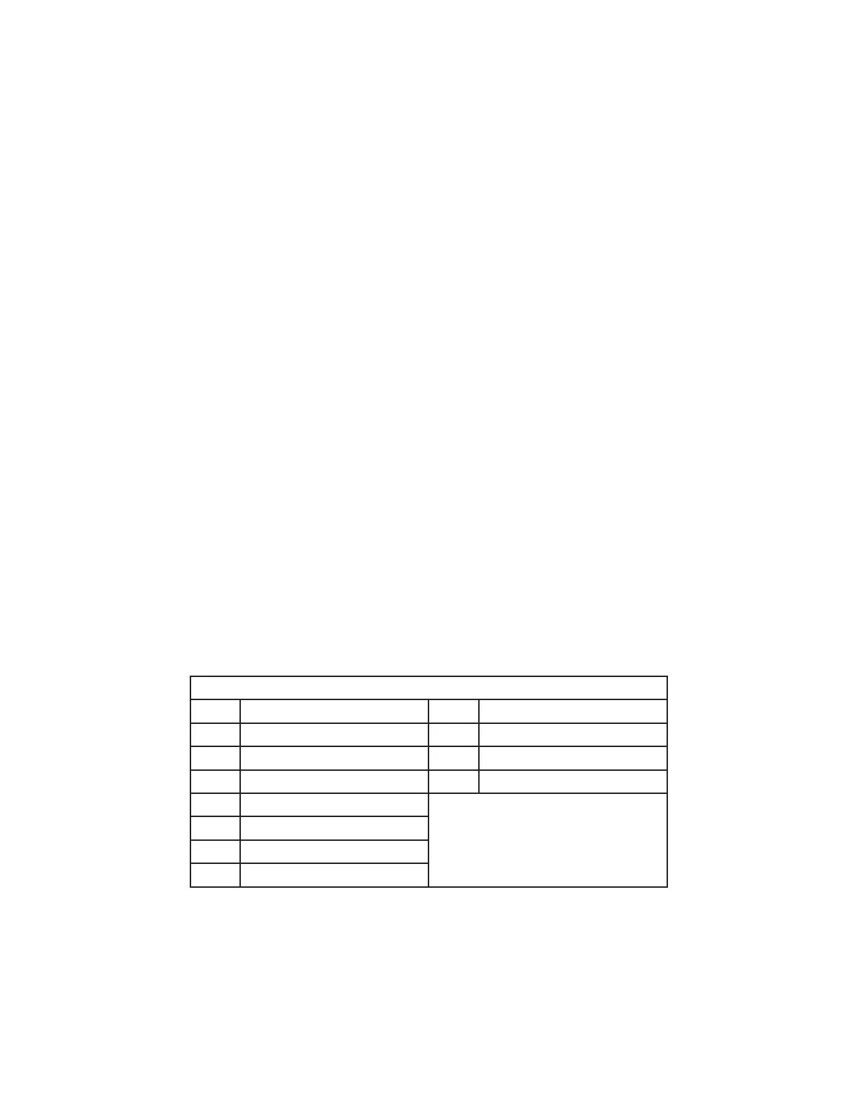
Unit Size Chart
0 = A96US2V045B12S-01 8 = A96DS2V045B12S-01
1 = A96US2V070B12S-01 9 = A96DS2V070B16S-01
2 = A96US2V090C12S-01 11 = A96DS2V090C20S-01
3 = A96US2V090C16S-01 U = A96DS2V110C20S-01
4 = A96US2V090C20S-01
5 = A96US2V110C16S-01
6 = A96US2V110C20S-01
7 = A96US2V135D20S-01