SPC 20 OPERATOR’S MANUAL
MAINTENANCE E-11
First, with a VOM (ignition off), determine the battery
voltage by connecting the negative lead to the (-) terminal
and the positive lead to the (+) terminal of the battery. The
meter should read ~12.6 V., or more if the battery is in
above average condition. Next, with the engine off,
determine if the solenoid is getting full battery voltage via
the interface plug. Loosen the Phillips head screw and
remove the square connector from the solenoid. Be careful
not to misplace the gasket between the solenoid and the
plug. Turn the ignition switch to the run (on) position.
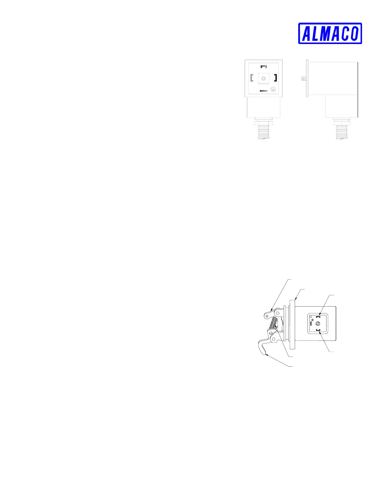
Using the VOM, attach the negative lead of meter to ground
(chassis) and positive lead to terminal 1 of interface
connector. (See FIGURE E-2) This reading should be the
same as the battery.
If full voltage is not present at terminal 1:
1. Check for voltage in and out of the main wiring harness interface connector. On the 1011
series this connector is located about 8 inches below and to the right of the solenoid plug. On
the 1011F series this interface is located about 3 inches above and to the left of the solenoid
plug. Pin #7 carries the power and Pin # 8 is the ground. Repair any problem found here as
necessary.
2. Check for voltage out of the ignition switch (IGN terminal, switch on). If there is no power at
the IGN terminal and there is power at the BAT terminal, replace the ignition switch.
3. Check the wiring from the ignition switch to the interface connector. Repair as necessary.
If 12 V. is present:
1. Using the VOM, check the resistance across terminals 1
and 2 (two C-shaped lugs) of the solenoid. (See FIGURE E-3)
There should be ~3 ohms.
2. If no resistance, replace the solenoid.
Second, check for good ground via the wiring harness). Set the
VOM to the lowest ohms (Ω) scale available and check for
resistance between chassis and terminal 2. The meter should
read 0. If not, check the battery ground connections, the
grounding of the wire coming out of the interface connector (#8),
and the pins in the interface connector at terminal #8. Repair as
necessary.
Solenoid; ALMACO #39151, Deutz #4270581
O-ring; ALMACO #39152, Deutz #1164748
1
2
3
MSD3
FIGURE E-2
LINKAGE ARM #1
LINKAGE ARM #2
RETURN SPRING
TERMINAL #2
TERMINAL #1
SOLENOID BODY
FIGURE E-3