Pro, Solo
INSTRUCTION MANUAL Page 8
SHAW-ALMEX INDUSTRIES LIMITED 49908-042 March 2012
4.4. Basic Assembly and Splice Preparation
Safety: The vulcanizer should be assembled and operated on a flat, level and stable surface so there is no
danger of falling.
1. Lower the pressure bolts and lift top frame from the bottom frame.
2. Prepare the splice as required.
3. Position splice on lower platen. It is good practice to use platen covers between the belt and the top and bottom
platens.
4. Position top frame on the bottom frame, aligning the top and
bottom frame.
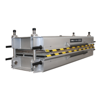
5. Raise the pressure bolts onto the top frame. They will be safely
in position when the top of the nut bears on the bearing cap and
the shoulder is under the edge of the frame, figure 2.
Safety: Failure to engage the pressure bolt properly could
result in over stroke damage to the vulcanizer and injury when
pressure is applied.
6. When using frame mounted temperature controls, connect the
panels to two separate power supply circuits. The temperature controller will illuminate, but the platen will not
start heating until the switch is on (1A-on, automatic or 1M- on, manual). See temperature control manual.
Safety: Each platen may have to be connected to a separate
circuit to avoid exceeding the current carrying capacity of the power
supply.
7. When using remote temperature controls, connect the top and
bottom platen electrical cables to the platen connectors and
connect the panel to a power supply. The temperature controller
will illuminate, but the platen will not start heating until the switch is turned to 1A (on, automatic) or 1M (on,
manual). See temperature control manual.
8. Connect the top and bottom platen cooling supply and drain hoses. To disconnect the hoses, pull back on the
collar on the quick connect plug.
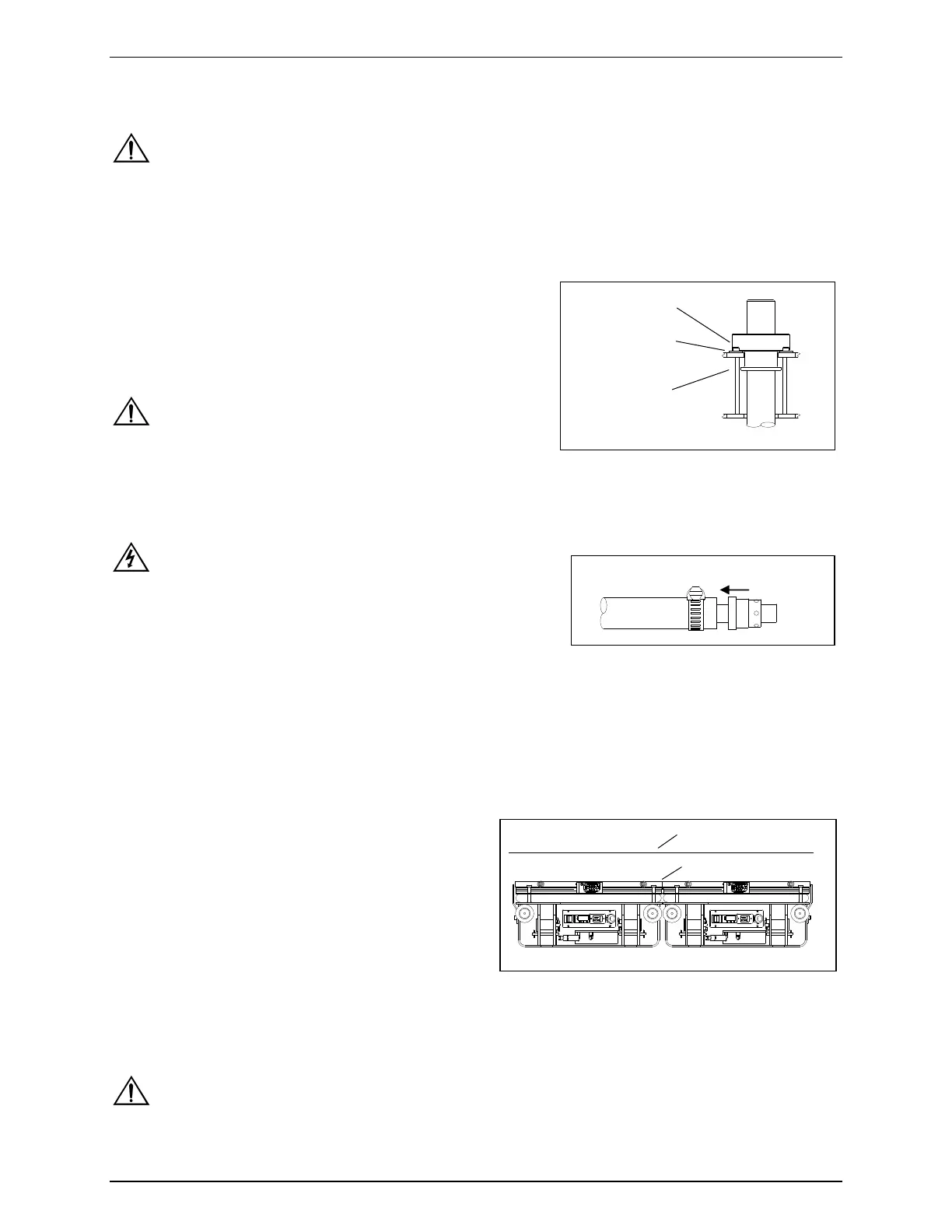
4.5. Assembling Presses Side by Side on a Splice
All Pro and Solo presses can be positioned side by side
with their platens touching in order to make a larger platen
area.
1. Remove the platen guard from the side(s) of the presses
to be used together by loosening the platen guard
assembly bolts.
2. Remove the platen covers by removing the screws from
the side of the platens.
3. Cover the top and bottom platen area with a 1/8" thick
(3 mm) metal cover plate (aluminum, steel or stainless
steel).
4.6. Changing Handle Position
The handles can be located on the sides or the end of the frame. Tighten by hand only.
Safety: When changing the handle position, be sure the handles are threaded all the way in.
Top of Nut
Bearing Cap
Shoulder of Nut
Figure 4
Figure 2
Cover Plate
Platens touching
Pull to release