SVP INSTRUCTION MANUAL Page 16
SHAW-ALMEX INDUSTRIES LIMITED 49909-010
Jun 2017
and therefore the threads should be re-coated before re-assembly. The surfaces should be free from dirt, oil,
grease, moisture and rust and the compound applied evenly to bolt threads.
6.2. Removing and Replacing the Platen Receptacle Insert
The contact pins in the platen insert should be inspected
occasionally for damage from wear, corrosion, or arcing.
If the pins are damaged, the insert must be replaced. The
cover should always be used when transporting or storing
the platens to keep the receptacle clean.
Important: The platen insert is made from a special
material capable of resisting the high platen temperature.
Contact SHAW ALMEX for the proper replacement part.
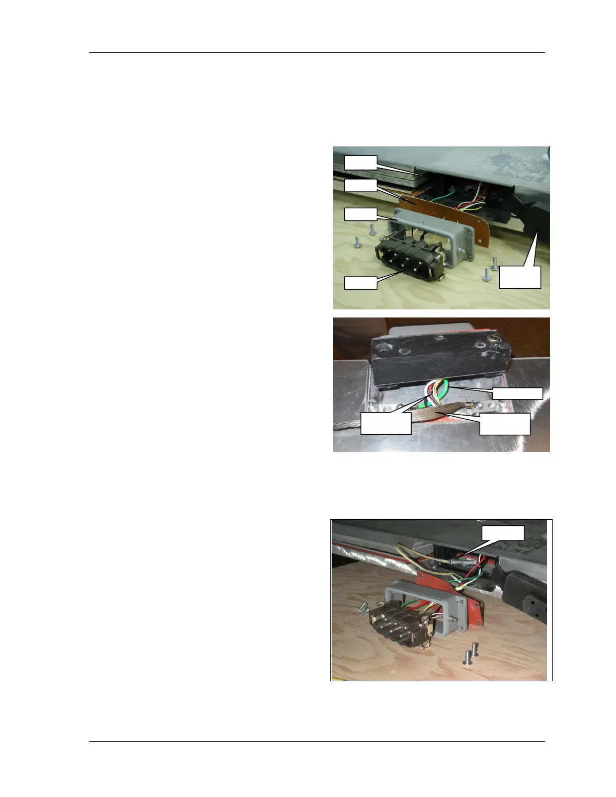
1. Remove the electrical connector housing from the
platen edge by loosening the four screws and
carefully pull the gasket, housing and insert away
from the platen.
2. Remove the insert from the housing by loosening the
four screws and carefully pull the wires through the
gasket.
3. Disconnect the RTD probe, element and ground
wires from the insert.
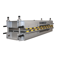
4. Attach all wires to the new insert. Connect the
yellow RTD probe lead to terminal 4 and the two
white wires to terminals 5 and 6.
5. Install the insert in the housing.
6. Hold the wires and slide the gasket along the wires
until is it against the housing.
7. Rotate the housing several times to wind the wires
into a loose bundle and then carefully bend the wires
into the adapter.
8. Make sure there are no wires pinched and fasten the housing to the adapter.
6.3. Replacing the Temperature Sensor (RTD Probe)
1. Remove the electrical connector insert from the
platen. See 6.2 Removing and Replacing the Platen
Receptacle Insert.
2. Disconnect the RTD probe wires from the insert and
pull through the gasket. The element wires can
remain connected.
3. Remove the RTD probe from the platen. See Figure
16 RTD Probe. If the probe does not come easily,
make a ¼” (6mm) hook on the end of heavy wire
and slide it down the channel to the bottom of the
probe (approximately 8” or 200 mm) and pull. If it
is not possible to pull out the probe it must be
drilled out with a ¼” (6 mm) diameter, 9 inch (230
mm) long drill.
4. Trim the wires on the new probe to the same length
as the old probe.
5. Insert the RTD wires through the appropriate holes in the gasket so the yellow wire aligns with terminal 4
and the two white wires with terminals 5 and 6. The probe wires should have small metal sleeves crimped to