SVP INSTRUCTION MANUAL Page 11
SHAW-ALMEX INDUSTRIES LIMITED 49909-010
Jun 2017
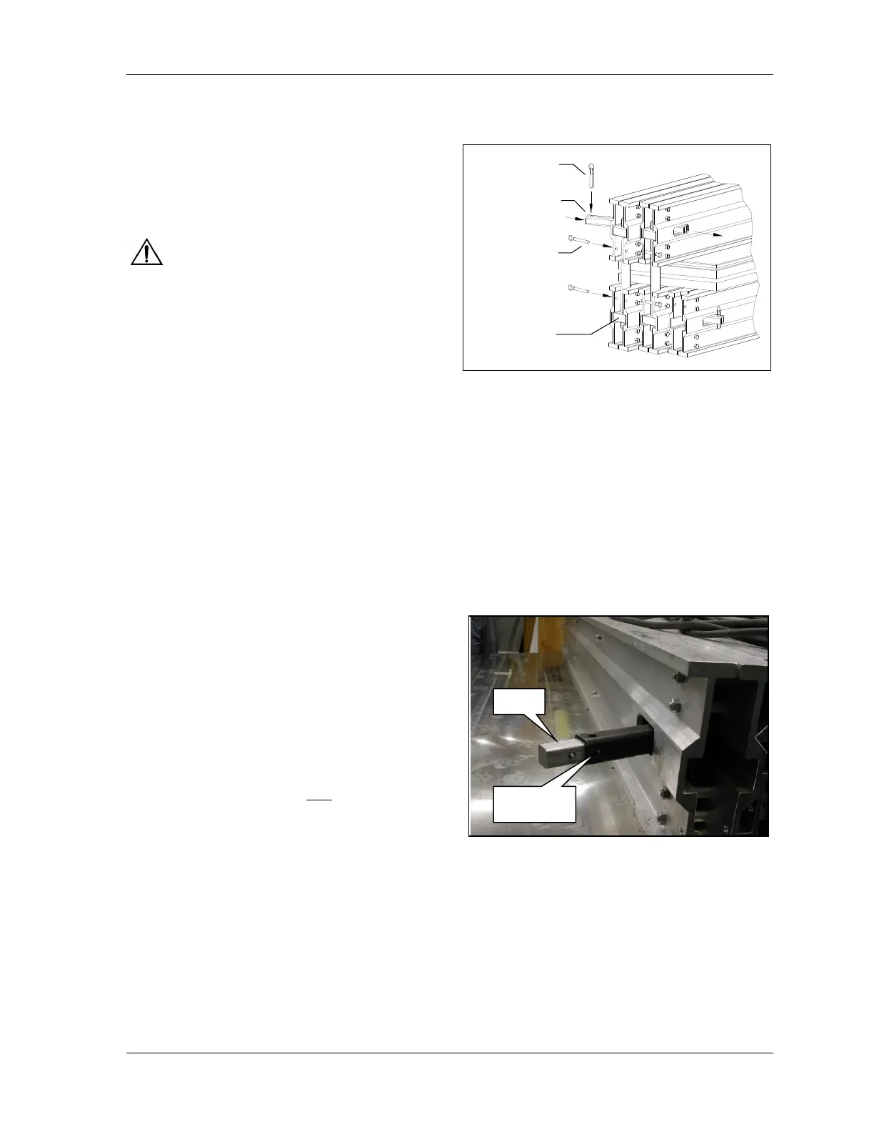
18. Install the restraining bars. With the gauge pin
removed from one end, slide the bar through each
traverse bar and install the gauge pin. Both gauge
pins should be approximately 3/4” (18 mm) from
the side of the outer traverse bars.
19. Install the bolt retaining pins through the holes in
the remaining upper and lower bars.
Safety: The restraining bars, gauge pins, and
bolt retaining pins are safety components. When used
together this feature will protect against hazards that
might result in the event of a bolt failure.
20. Adjust the edge irons.
21. Position the temperature controls and pressure
controls at the splice location.
22. Make electrical, pressure and cooling connections as shown on the General Arrangement drawing at the
back of this manual. If unfamiliar with this procedure, refer to the manuals for the temperature controller
and the pressure controller.
23. Connect the top and bottom platen electrical cables to the temperature controller and connect controller to
power supply. See temperature controller manual.
24. Connect the top and bottom platen cooling supply and drain hoses.
4.6. Assembly of Multiple Platens
Multiple platen Sectional Vulcanizers are designed so the platens can be placed side by side to make a larger
platen area. The assembly procedure is the same as described above, with the following additions.
1. The template will be in more than one section on arrangements over 96” (2.4 m).
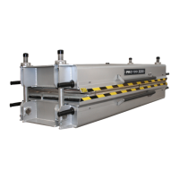
2. The restraining bar will be in more than one section
on arrangements over 96” (2.4 m). Join the
restraining bar sections using the union as shown.
The union is properly installed when the spring
plunger is engaged in the countersunk hole. Install
the lower restraining bars as the traverse bars are
moved into position because it can become difficult
if the traverse bars are not at the same height.
3. Install the lower platens on the lower bars with the
edges tight together.
Tip: It is good practice to use two 1/8 inch (3 mm) steel
plates the same size as the total platen area when
splicing with multiple platens. One plate is used on
top of the lower platens and the other plate is used
on top of the belt (below the upper platens). The
steel plates ensure that no rubber flows between the platen joint. Always try to locate the pressure bags so
that the joint between bags does not coincide with the joint between platens.
4. Install the upper platens aligned with the lower platens and with the edges tight together. The insulation is
made smaller than the platen so the platen edges come together. Be sure that the gap between the platen
insulating panels does not exceed 3/8” (9 mm) or the bag will try to expand into the gap.
5. Install the pressure bags so the valves are on the same side or as close as possible. Always try to locate the
pressure bags so that the joint between bags does not coincide with the joint between platens. When platens
are all the same size on multiple arrangements, two half bags will be supplied so the bag and platen joint do
not coincide.