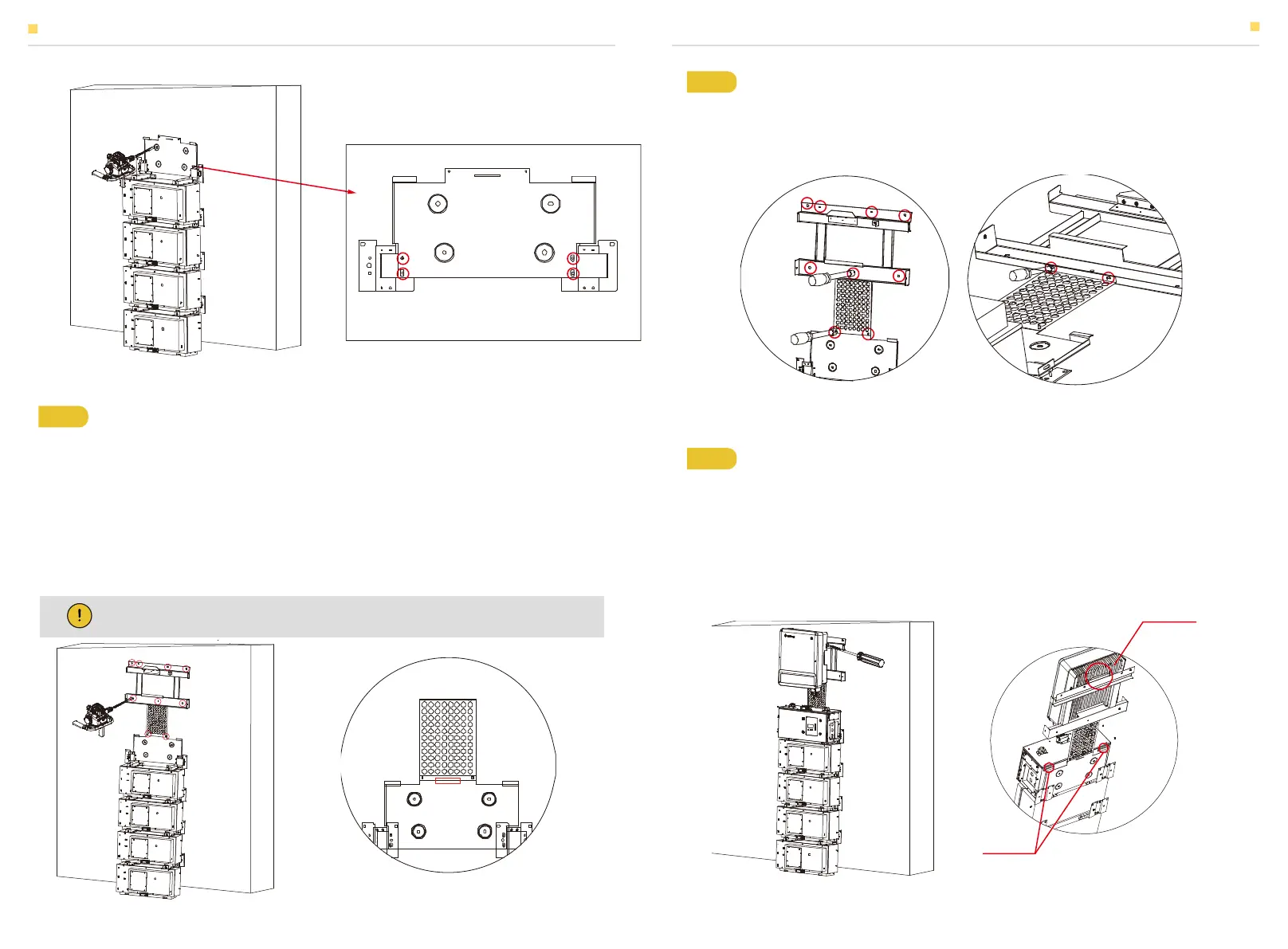
Figure 19 Fixing the Rear Bracket of HV50056
Figure 21 Installation of the Bracket A of the Inverter
Figure 22 Installation of the HV50056 and the Inverter
Figure 20 Fixing of the Rear Bracket of HV50056
Step 7 Fix the HV50056 rear bracket as shown in Figure 16.
1 Find the positioning point and mark it.
2 Use the impact drill (drill φ10.0mm, length 20cm) to directly drill the hole in the marking position
of HV50056 rear bracket, the depth of the drilled hole should be 7cm.
3 After the drilling is completed, insert the expansion tube into the drilled hole, and fix the rear
bracket with a 10mm self-tapping screw by using 10MM sleeve (SW10).
4 Fix the HV50056 box rear bracket with the flange nut and use a 7MM sleeve on the two L-shaped
brackets of the battery (SW7).
Step 9 Fix the inverter B bracket as shown in Figure 19.
1 Find the positioning point and mark it.
2 Use the impact drill (drill φ10.0mm, length 20cm) to directly drill the hole in the marking position,
the depth of the hole is about 7cm.
3 After the drilling is completed, insert the expansion tube into the drilled hole, and fix the bracket
B with a 10mm self-tapping screw by using 10MM sleeve (SW10).
4 Fix bracket B with the flange nut and use a 7MM sleeve on the two L-shaped brackets of the
battery (SW7).
Step 8 Fix the bracket A of the inverter on the rear bracket of HV50056 with the flange nuts, as
shown in Figure 18.
The bottom of the bracket A shall be placed at the same horizontal line with the rear bracket of
HV50056.
INSTALLATION INSTRUCTIONS
INSTALLATION
NOTE: Place the PE bag on the battery to block out the dust before drilling.
15 16
Hanging Position for the Inverter
Hanging positions for the HV50056


 To Next Page