
K
Kristopher EdwardsAug 4, 2025
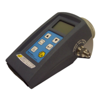
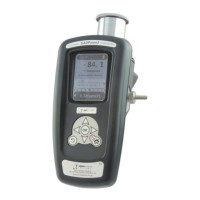
Why is my Alpha Moisture Systems dewTEC DS2000 showing a wet reading?
- JJoshua PriceAug 4, 2025
If your Alpha Moisture Systems Measuring Instruments shows a wet reading, it could be due to a leak in the system or the use of unsuitable piping. It may also arise from comparison with a secondary standard instrument or calibration gas. To address this, fix any leaks or replace unsuitable pipes with copper or stainless steel, using PTFE pipe for flexible connections, and avoiding rubber or plastic. Ensure samples are taken from the same point. Re-check the Autocal setting. If problems persist, recalibration of the system is recommended.