Alpha 9500 HF Linear Amplifier Operating Manual Alpha Radio Products
Amplifier Components Product Release 1
DOCNUMBER 9500
Document Issue 1, Revision 7
Page 2–4 June 2009
22
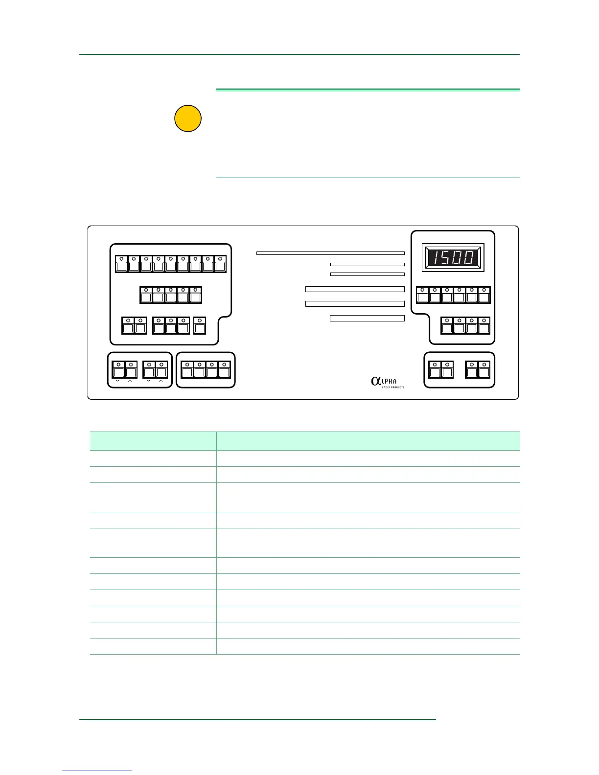
IMPORTANT Note that the front panel has, in the upper-right corner, a 7-segment
LED display (so named because one can, by individually turning on
or off each of just 7 simple bars, display any single digit 0 to 9). The
display contains 4 such digits.
The buttons below the display control wh
at kind of value is displayed:
FLT, Fwd, Ig, Ip, SWR, or Vp.
Figure 2-4 Amplifier controls
BAND
MEMORY
SAVE RCL DEF 1 2 AUTO
TUNE LOAD
ANTENNA SELECT
1.8 3.5 7 10 14 18 21 24 28
12345
1234
RF Power kW
SWR
Grid Current mA
Plate Current Amps
Plate Voltage kV
Gain
0 0.1 0.3 0.6 1.0 1.5 2.5
1 1.5 2 3 >10
0 50 100 150
0 1.0 1.5
02314
10 30 50
MICROPROCESSOR CONTROLLED HF LINEAR AMPLIFIER
ALPHA
Fwd IpVpIg SWR FLT
DIM SND PEP DEL
OPER STBY ON/OFFON
ANT SELAMP
SEGMENT
9500
Table 2-1 Amplifier Buttons (listed alphabetically)
Button Purpose
ANTENNA SELECT Determines which one or two of the four antenna output ports to use.
BAND Selects an amateur band, design
ated in megahertz (MHz).
DEL Displays the delivered power from the
amplifier to the selected antenna
port in watts (W).
DIM Controls the brightness of the display LEDs.
FLT Sets the 7-segment display to show the last fault. Also loads new
fir
mware.
Fwd Sets the 7-segment display to show forward power in W.
GAIN Displays the gain in decibels (dB).
GRID CURRENT Displays the grid current in milliamperes (mA).
Ig Sets the 7-segment display to show grid current in mA.
Ip Sets the 7-segment display to show plate current in mA.
LOAD Controls the load capacitor.