DOCNUMBER 9500
Document Issue 1, Revision 7
June 2009 Page 2–3
Alpha Radio Products Alpha 9500 HF Linear Amplifier Operating Manual
Product Release 1 Amplifier Components
2.2 Center-Partition Board
The center-partition board contains the RF decoupling circuit on the B+
line as well as the crowbar safety circuit. When you remove the top cover
of the ALPHA 9500, the spring metal of this safety device shorts out the
B+ line.
2.3 Connections
When the ALPHA 9500 is powered up, it measures the line voltage and
chooses, then sets the appropriate tap setting for the transformer primary.
After it is powered up, it does not reset the tap. The amplifier can be set
to override autotaps election and use any primary tap; it may be useful to
do so if your line voltage is unsteady or on the edge of a tap setting. For
more information, contact ALPHA technical support.
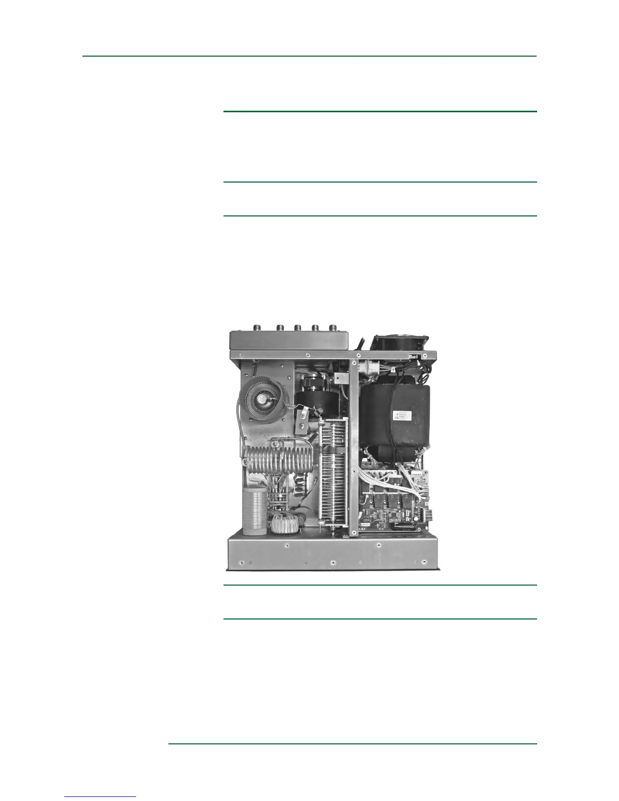
Figure 2-3
Primary connections
2.4 Controls and Display
The ALPHA 9500 controls enable you to adjust and monitor the amplifier
as needed (see Figure 2-4).