DOCNUMBER 9500
Document Issue 1, Revision 7
June 2009 Page 2–7
Alpha Radio Products Alpha 9500 HF Linear Amplifier Operating Manual
Product Release 1 Amplifier Components
2.9 Power Supply
The power supply has two major sections: a switch-mode supply for the
logic circuitry and a conventional transformer supply for all other
voltages.
When the amplifier is plugged into the AC line, the switch-mode supply
is al
ways on and all the microprocessors are active. It is usual for some of
the front panel LEDs to blink momentarily when the unit is first plugged
in.
The remaining voltages are produced by the
mains and HV boards,
described below.
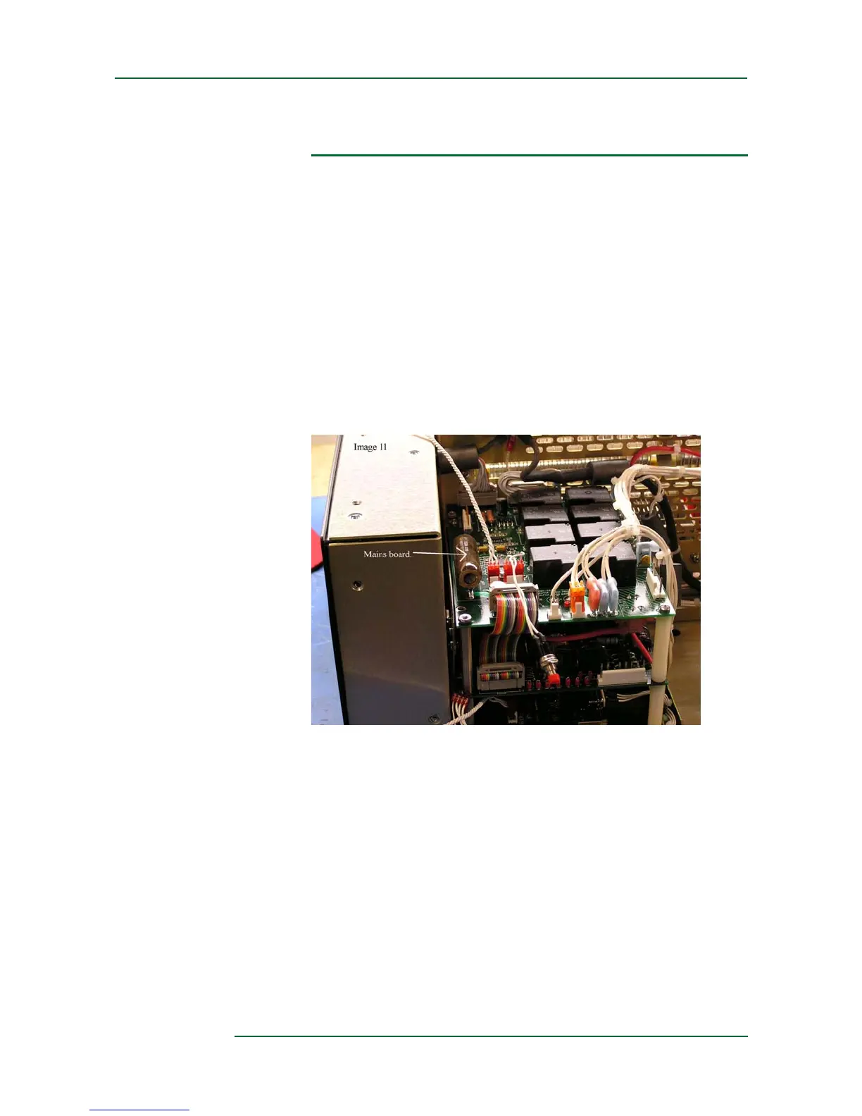
Mains Board
Figure 2-5 Mains board
Power-supply functions are split between the mains board and the HV
board. The mains board deals mostly with the primary side of the
transformer. The various taps for the transformer primary are routed
through this board and so is the AC line input. Relays on the mains board
connect the AC line to the appropriate taps on the transformer primary.
When the ON (AM
P) button is pressed, the microprocessor on the mains
board samples the line voltage and determines which tap to select. That
voltage tap remains selected until the amplifier is turned off, and does not
change even if the line voltage fluctuates.