Alpha E-Tec Plus 28NX, 33NX and 38NX - Installation
5.9 EXTENDING THE FLUE - Fig. 5.13
Note: - The flue assembly length must not exceed the maximum length stated, including the equivalent lengths
of any extensions, bends etc. used for plume management components. E-Tec boilers must not exceed the
maximum of an equivalent horizontal flue length of 12 m.
1. When the flue length required is more than the maximum stated in Section 5.7, the Alpha 750 mm flue extension (Part
No. 3.031807), 1000 mm extension (Part No. 3.031808) or 2000 mm extension (Part No. 3.031814) are required to
extend the range of telescopic flue. Refer to Section 5.9 for instructions on how to extend the flue.
Note: A 130 mm flue hole (127 mm core drill) may be required in the wall. This is when the extended flue is passed
through the wall.
Each extension used must be supported with the bracket supplied with the extension. If necessary the bracket M8
threaded stud can be replaced with a longer one (not supplied).
Additional support brackets are available if required. (Part No. 3.034521).
2. Use the template (supplied with the boiler) to mark the required flue position, ensuring there is the correct slope towards
the boiler.
3. Determine the overall flue length to calculate the number of Alpha flue extensions required.
4. When assembling the flue components, lubricate the seals with the lubricant provided before connecting the parts
together. Ensure both the inner and outer ducts are fully engaged.
Note: If it is required to cut an extension, DO NOT cut the end of the inner duct that incorporates the seal joint. Ensure
the inner and outer ducts are cut flush. Ensure that all cuts are square and free from burrs.
Once assembled with the components pushed home, the flue is fully sealed.
5. Adjust the telescopic section of the Easy-Flue to the required length and secure the Easy-Flue with the sealing tape
supplied. Fit the Easy-Flue to the extensions, ensuring both the inner and outer ducts are fully engaged.
6. Mark the end of the flue assembly 'TOP' where it is connected to the boiler, so that the 'TOP' of the flue terminal is
aligned with the 'TOP' at the boiler end of the flue assembly.
7. Pass the complete flue assembly through the wall.
8. Fit the inside (white) flue sealing collar over the Easy-Flue. If it was not previously fitted, fit the outside (black) flue
sealing collar onto the flue immediately before the terminal grille onto the location provided.
9. Place the flat concentric gasket (supplied with the boiler) onto the boiler, ensuring the protruding 60mm rib is facing
downwards and located correctly.
10. Fit the bend to the flue turret supplied with boiler onto the Easy-Flue, fully engaging both inner and outer duct.
11. Check the flat concentric gasket is still in the correct position and fix the flue turret to the boiler with the 4 screws
(supplied with the boiler).
Refer to Section 5.6, Fit the flue turret.
12. Using a Flue Gas Analyser (FGA), carry out a flue integrity test. If readings are unacceptable, remove flue and check all
joints before carefully re-assembling and repeating the test
Note: Check the flue terminal protrudes 120 mm out of the wall and the inner duct of the terminal is positioned correctly
(see Fig. 5.13).
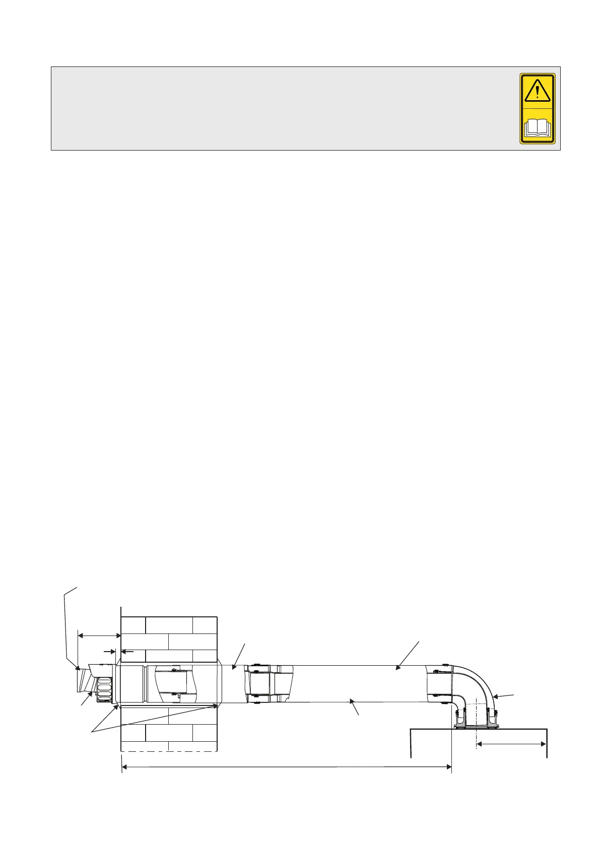
Fig. 5.13 - Push fit side flue
Front of boiler
Flue length (L)
Easy-Flue
Ensure the flue extension slopes
downwards towards the boiler by a
minimum of 25 - 30 mm per metre
Flue extension
Flue sealing
collar
Ensure the inner duct within the terminal is at the top.
The inner duct must be positioned to slope towards the boilerNote:
120
Terminal
20
220
90° bend
23