When commissioning the boiler, ensure the Benchmark Checklist at the back of these instructions is
completed.
6.1 FILL THE SYSTEM
1. The boiler is fitted with an automatic air vent positioned on the pump (see Fig. 7.8), ducted to the bottom of the boiler
casing and is not to be blocked.
2. Open the central heating flow and return valves (operating lever in-line with valve) (see Fig. 5.4).
3. Open the fill point valves on the filling loop until water is heard to flow (see Section 4.7).
4. To remove the air - Vent each radiator in turn, starting with the lowest in the system.
5. Check the operation of the safety valve (see Fig. 7.8) by turning the head anti-clockwise until it clicks. The click is the
valve lifting off its seat allowing water to escape from the system - check that this is actually happening.
6. Continue to fill the system until the pressure gauge indicates 1.0 bar. Close the fill point valve and check the system for
water soundness. Disconnect the filling loop from the mains supply.
Water may be released from the system by manually opening the drain point (see Fig. 7.8) until the system design
pressure is obtained. The system design pressure (cold) should be between 0.75 and 1.25 bar.
Refer to Sections 4.7 and 4.8. Filling and Flushing the system.
7. Open the cold water mains inlet valve (see Fig. 5.4). Turn on all hot water taps and allow water to flow until no air is
present. Turn off taps.
8. Ensure that the condensate trap has been filled with water.
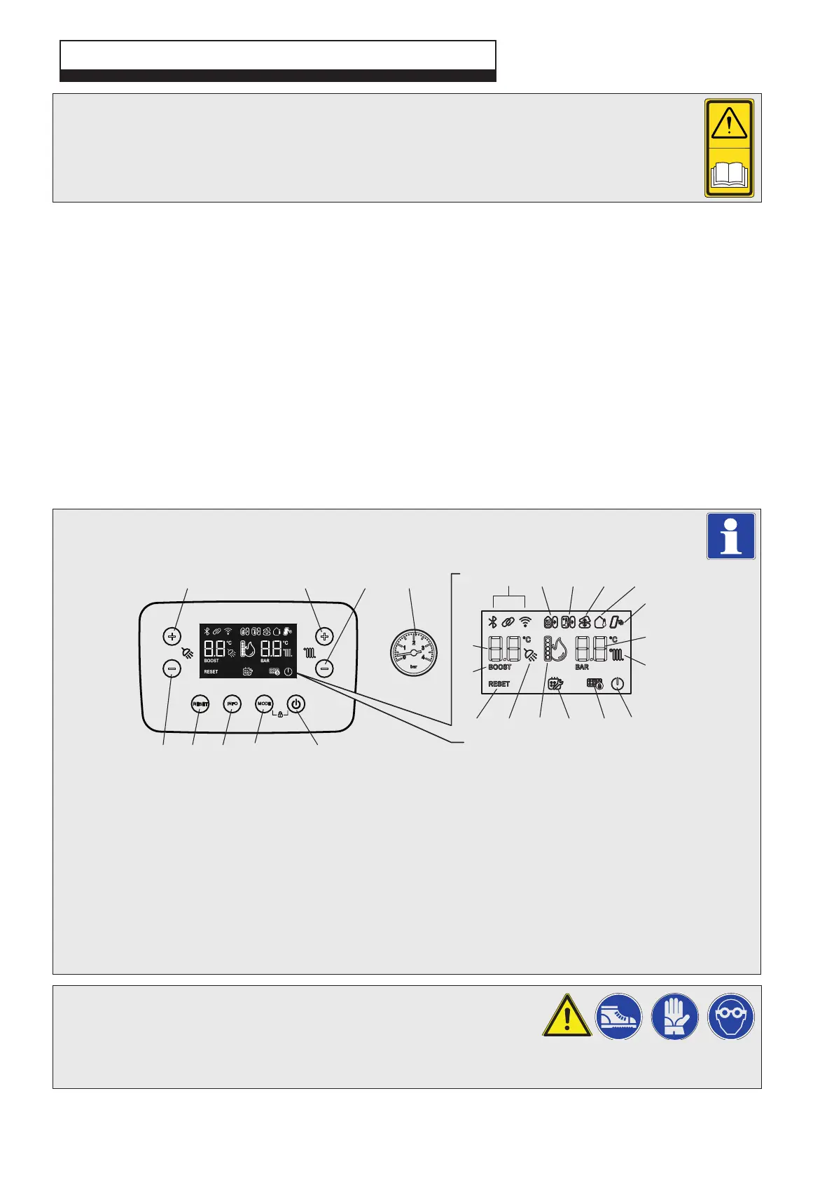
6.2 CONTROL PANEL FEATURES - Fig. 6.1
Alpha E-Tec Plus 28NX, 33NX and 38NX - Commissioning
6 COMMISSIONING
Fig. 6.1
6.3 TEST FOR GAS TIGHTNESS AND PURGE THE SUPPLY
1. With the boiler connected, pressure test the gas supply and inlet pipework
connected to the boiler for tightness in accordance with BS 6891.
2. Loosen the gas inlet pressure test point screw on the gas valve (see Fig. 6.2) and purge in accordance with BS 6891.
3. Retighten the test point screw and test for gas tightness. Close the boiler gas service cock.
1 ON/OFF button
2 Operating mode button
3 Information button
4 Reset button
5 Decrease DHW set temperature
6 Increase DHW set temperature
7 Increase heating system set
temperature
8 Decrease heating system set
temperature
9 Heating system pressure gauge
10 Not used on this model
11 Not used on this model
12 Remote Climatic controller fitted
13 External server connection
14 External weather probe fitted
15 Active solar supply (pre heated inlet)
16 Heating system set temperature
17 Heating enabled (fixed) or active (flashing)
18 Boiler in OFF mode (flashing) or stand-by
(fixed)
19 Keyboard lock active
20 Programmed service request
21 Flame presence symbol and relative output
scale
22 DHW production enabled (fixed) or active
(flashing)
23 Reset button
24 BOOST function active
25 DHW set temperature
When using the control panel buttons, first activate the keyboard by pressing any button, then press the
desired button to activate the desired function.
Note: Pressing buttons 1 and 2 together for five seconds will activate or deactivate the keyboard lock.
32
MODEINFO
RESET
+
-
+
-
12345
67
11
18202223 21 19
15
16
17
24
25
12 13 1410
98