Alpha E-Tec Plus 28NX, 33NX and 38NX - Technical Data
3.3 FLUE LENGTHS
A 500 mm or 1000 mm Easy-Flue terminal kit with 90° bend or horizontal terminal is available.
CD 750 mm and 1000 mm flue extensions are available.
Length of Flue Required:-
Rear Flue = wall thickness + 180 mm (includes terminal).
Side Flue = wall thickness + distance between wall and side of boiler + 265 mm (includes terminal).
Vertical Flue = distance from top of boiler side panel to required roof position minus 1000 mm for vertical terminal assembly.
Maximum horizontal flue length = 12 m.
Maximum vertical flue length including terminal is 14 m.
Each additional CD 90° Bend is equivalent to 1.3 m of flue length.
Each CD 45° Bend is equivalent to 0.9 m of flue length.
The CD Vertical Flue terminal assembly is equivalent to 1 m of flue length.
3.4 PUMP
The boiler is equipped with a variable speed low power consumption pump.
During the DHW mode, the pump always runs at the maximum speed.
During the CH mode, three different functioning modes of the pump are available, Proportional, Fixed and Constant T.
Proportional - The pump speed is controlled automatically in order to give a proportional pump head, the pump speed
varies based on the heat output supplied by the burner - the greater the heat output the higher the pump
speed. See parameter A.4 in Section 6.14.
It is possible to adjust the pump speed range in the boiler parameter menu.
Fixed - The pump runs at a constant speed by setting the same minimum and maximum speeds. See parameters
A.2 and A.3 in Section 6.14.
Constant - The pump speed is controlled to give a set T. See parameter A.4 in Section 6.14.
The boiler is factory set to Constant - to achieve a T of 15°C (parameter A.4 is set to 15)
By-pass Regulation - The boiler leaves the factory with the by-pass open.
If necessary, the by-pass can be adjusted to the system requirements from maximum (by-pass open) to minimum
(by-pass closed). Adjust using a flat head screwdriver, turn anticlockwise to close the by-pass, and clockwise to open.
With the by-pass in the closed position the system must have a continuous open circuit.
If zone valves are used in the system an external by-pass must be fitted.
When the pump is running, the symbol
flashes with green light.
When the pump power supply on, the symbol
is steady with green light.
If the pump detects an alarm, the symbol
is steady with red light.
Note: OtherTechnical data is the same as NG data.
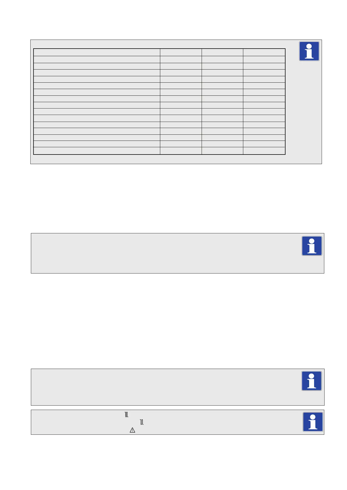
3.2 TECHNICAL PERFORMANCE DATA - LPG - PROPANE GAS (Cat I3P 3P - G31 37 mbar)
Heat input gross - DHW kW
Heat input gross - CH kW
Heat input minimum gross kW
Gas supply pressure nominal (minimum) mbar
Gas burner injector mm
CO2 at maximum DHW output %
CO2 at minimum output %
Gas rate at maximum output kg/h (g/s)
SAP/SEDBUK seasonality efficiency 2005 %
SAP/SEDBUK seasonality efficiency 2009 %
CO (maximim) ppm
Flue mass at maximum output Kg/h
Flue mass at minimum output Kg/h
Flue temperature at maximum output °C
Flue temperature at minimum output °C
31.2
26.6
4.9
37 (32)
3.70
10.2 (10.0 - 10.4)
9.7 (9.5 - 9.9)
2.23 (0.62)
90.8
89.5
250
48
8
69
56
35.5
31.1
5.4
37 (32)
4.20
10.3 (10.1 - 10.5)
9.6 (9.4 - 9.8)
2.54 (0.71)
90.7
89.4
250
54
9
79
61
E-Tec Plus 28NX E-Tec Plus 33NX
E-Tec Plus 38NX
41.3
35.5
6.5
37 (32)
4.90
10.0 (9.9 - 10.3)
9.4 (9.1 - 9.5)
2.95 (0.82)
90.6
89.3
350
64
11
85
64
7