Alpha E-Tec Plus 28NX, 33NX and 38NX - Technical Data
Note: This Appliance Must Be Earthed
Optional integral single channel controls are available if required.
Note: Only use the Alpha single channel controls. Do not fit any two channel controls.
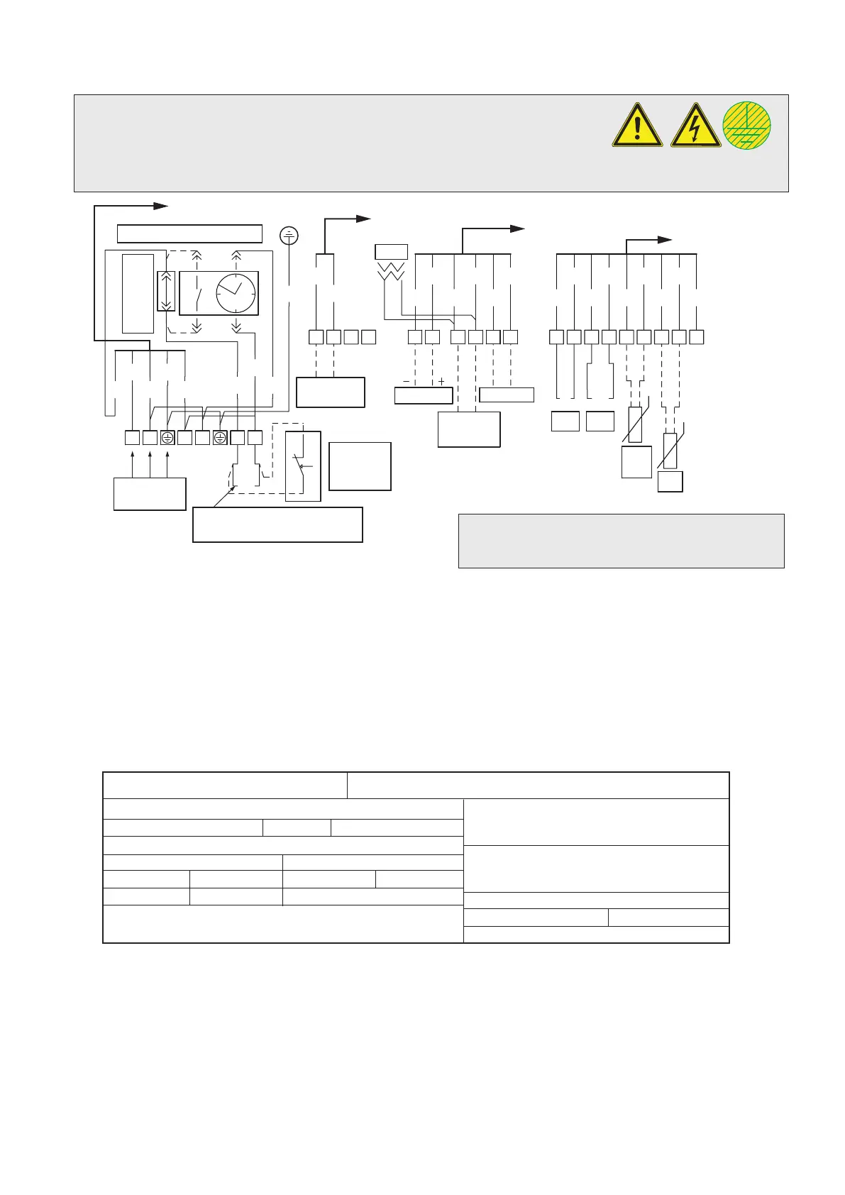
3.6 ELECTRICAL CONNECTIONS
Fig. 3.3
3.7 DATA BADGE ANNOTATION
Md
Sr N
o
Type
Q
nw/Qn min.
PMS
NO
x Class
Q
nw/Qn max.
PMW
Cod. Md
Cod. PIN
P
n min.
D
P
n max.
TM
CONDENSING
Md.............................Model
Cod. Md ....................Model code
Sr N
o
.........................Serial number
CHK ..........................Check
Cod. PIN ...................PIN code
Type ..........................Type of installation (ref. CEN TR 1749)
Q
nw min. .....................DHW minimum heat input
Q
n min. .......................CH minimum heat input
Q
nw max. ....................DHW maximum heat input
Q
n max. ......................CH maximum heat input
P
n min. .......................Minimum heat output
P
n max. .......................Maximum heat output
PMS ..........................Maximum system pressure
PMW .........................Maximum DHW pressure
D ...............................Specific flow rate
TM ............................Maximum operating
temperature
NO
x Class .................NOx Class
CONDENSING .........Condensing boiler
NOTE: Technical data is provided on the boiler data label and in Section 3.1.
See Section 5.5 for position of Data label.
B4 ...... External sensor (optional)
B9 ...... DHW inlet sensor (optional) set P.15 = 1
B1-2 ... System flow sensor (optional) set P.15 = 2
X70 .... Safety thermostat low temperature link (configurable)
X80 .... Configurable input 1 link
When an Alpha Climatic control is connected
to terminals 44 and 41 remove the link
between terminals 1 and 2
Bl ....... Blue
Bk ...... Black
Br ....... Brown
Gy ...... Grey
G/Y .... Green/Yellow
Or.......Orange
P ........ Purple
R ........ Red
Colour code
W ....... White
Y ........ Yellow
X8 on PCB
X9 on PCB
X10 on PCB
X14 on PCB
Programmer clock (optional)
Remove link to
connect clock
Mains Supply
230 V ~ 50 Hz
Remove link to connect 230 V
room thermostat or BUS control
Room
thermostat
(optional)
3
1
4
2
+t
L
NAB
12
5
6
24
25
44
D+ D-
41
Aux output
Congurable
relay
MODBUS
Alpha BUS
(OT)
TEST
X70 X80
B4
B9
B1-2
14
15 40
41 47
48 38 39
21
G
GP
PY
Y
Or
Or
Gy
WBk
Bk
R
Br
Bl
Y
G
P
Bl
G/Y
Bk
R
Br
Bl
G/Y
Bk
Br
RBl
LN
GND 24Vdc
+
-
9