18
4.3 PREPARE THE WALL - Fig. 4.3
1. Decide upon the position of the boiler taking into account the clearances
required for servicing (refer to Section 2.2) and the ue terminal position.
2. Tape the template to the wall (ensure it is level and the right way up)
and mark the position of the two holes for the boiler mounting hooks.
3. Drill the xing holes (12 mm dia.) to accept the No. 12 plugs supplied.
Screw the boiler mounting hooks fully into the plugs.
4. Cut suitable holes in the wall/roof 100 mm dia for open ue 80 mm dia.
pipe or 127 mm dia. for concentric ue. Use the centre line positions
given on the ue template.
For side ue follow the horizontal line (ensuring at least a 25 mm/m
fall towards the boiler) to the corner then 140 mm along the side wall
to the centre of the hole for the ue.
5. Lift the boiler and locate it on the mounting hooks.
Note: When handling or lifting always use safe techniques - keep your
back straight, bend your knees, don't twist - move your feet, avoid
bending forwards and sideways and keep the load as close to your body
as possible.
Where possible transport the boiler using a sack truck or other suitable trolley.
Always grip the boiler rmly, and before lifting feel where the weight is
concentrated to establish the centre of gravity, repositioning yourself as
necessary.
Fig. 4.2
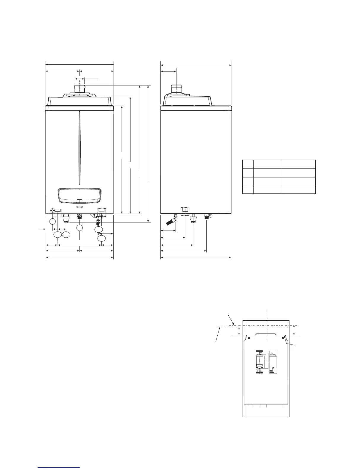
4.2.2 Pro Tec 70, 90, 115
A
B
C
Pro Tec 70
502 mm
265 mm
497 mm
Pro Tec 90, 115
632 mm
410 mm
627 mm
SV
HF
HR
80 Dia.
60
G
CD
E
608
304304
140
A
134
220
291
B
C
960
1038
1140
1219
75
105 390
300
600
300
105
131
E - Electrical connection
G - Gas supply
HR - Heating return
HF - Heating ow
CD - Condensate drain
SV - Safety valve outlet (tundish)
Fig. 4.3
Centre line for
vertical flues
Centre line
for horizontal
concentric flue
Centre line
for horizontal
open flue