19
Alpha Pro Tec - Installation
4.4 CONNECT THE PIPEWORK - Fig. 4.4
1. Thoroughly ush out all the system pipework. Refer to Section 3.10.
2. Connect the system ow and return pipework to the boiler using suitable
isolating valves.
Note: Do not forget that the pressure relief valve discharge pipe must be routed
clear of the boiler to a drain in such a manner that it may be seen, but cannot
cause injury to persons or property.
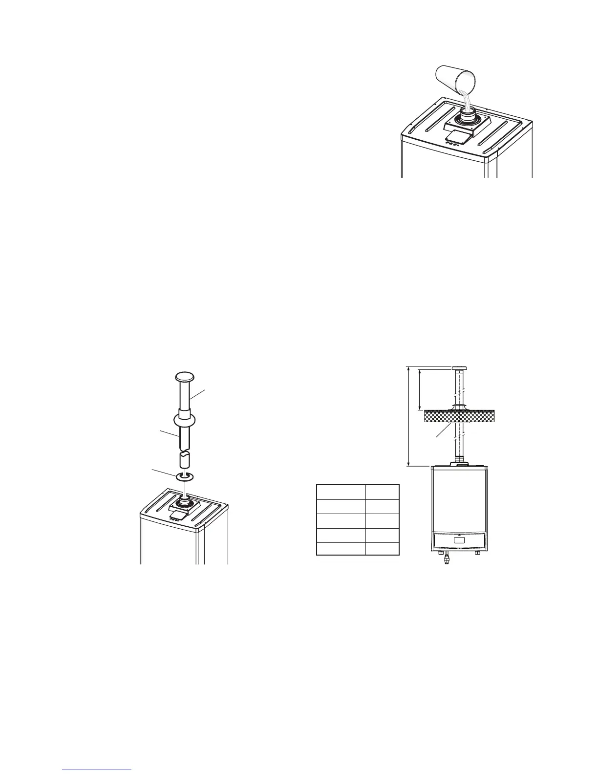
3. Connect the 22 mm condensate trap drain pipe to the condensate discharge
pipe using the clip supplied.
Ensure that the condensate discharge pipe is as required in Section 3.11.
Pour at least 1 litre of water into the ue duct, as shown in Fig. 4.4, and check
the condensate discharge pipe for soundness
4. Ensure that all the valves are closed and do not turn on the water or gas
supplies at this stage.
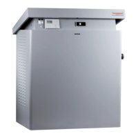
4.5 'B23' TYPE SINGLE PIPE 80 mm FLUE KITS
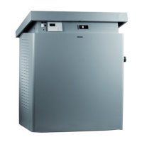
Vertical kit - see Fig. 4.5 and 4.6, and refer to Section 3.4.
Fig. 4.5 shows the vertical ue kit parts.
To assemble the kit to the boiler - Slide the ue pipe down through the roof seal and place the seal over the ue duct. Push
the ue duct into the ue socket on top of the boiler up to the stop. Ensure the seal is pushed in position against the ceiling.
To install extensions or other ue components, proceed as follows: t the male end of the pipe or elbow up to the stop on the
female socket (with lip seals) of the previously installed component, this will ensure a secure t and seal of the joints. Ensure
all joints have the seal located correctly and the tape supplied is applied around each joint to ensure the ue ducts cannot be
pulled apart.
It is recommended that the ue should be supported at least every 1.5 m with access provided to the joints.
Fig. 4.5 Fig. 4.6
Horizontal through the wall kit - see Fig. 4.7 and 4.8, and refer to Section 3.4.
Figs. 4.8 and 4.9 show the horizontal through the wall kit parts.
To assemble the kit to the boiler - Fit the male end of the ue elbow into central ue outlet on the top of the boiler to the stop.
Place the outer seal over the ue duct and slide it through the wall from the outside. Place the inner seal over the ue duct
then insert the duct into the elbow up to the stop. Slide the seals along the duct to seal it to the inside and outside of the wall.
To install extensions or other ue components, proceed as follows: t the male end (smooth) of the pipe or elbow up to the
stop on the female socket (with lip seals) of the previously installed component, this will ensure a secure t and seal of the
joints.
Note: To prevent condensate lying in the ue pipe, slope the pipe towards the boilers with a minimum slope of 2.5° - 3° (25 -
30 mm per metre). When installing the extensions, a wall/ceiling mounted clamp must be installed at least every 1.5 metres.
Fig. 4.4