Fig. 4.7
Fig. 4.8
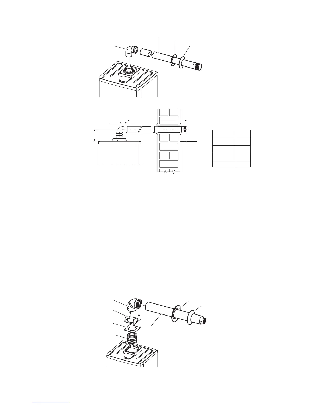
4.6 'C' TYPE CONCENTRIC FLUE KITS
Convert the boiler from the factory supplied 'B23' type conguration to 'C' type, i.e. room sealed concentric ue by removing
the 80 mm dia. adaptor and four screws securing the xing plate and gasket from the top of the boiler.
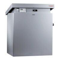
Horizontal through the wall concentric ue kit - see Fig. 4.9 and 4.10.
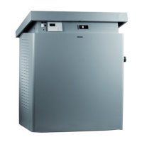
Fig. 4.9 shows the ue kit parts that need to be tted to the boiler to ensure the room sealed concentric ue can be used.
To assemble the kit to the boiler - Fit the adapter into the central ue outlet on the top of the boiler up to the stop. Slide the
square gasket over the adapter up to the groove, then x it to the cover by means of the previously removed xing plate and
four screws. Fit the male end of the ue elbow up to the stop on the adapter. Place the outer seal over the concentric ue
pipe and slide it through the wall from the outside. Place the inner seal over the concentric ue pipe then insert the pipe into
the elbow up to the stop. Slide the seals along the duct to seal it to the inside and outside of the wall.
To install extensions or other ue components, proceed as follows: t the male end (smooth) of the concentric pipe or
concentric elbow up to the stop on the female socket (with lip seals) of the previously installed component, this will ensure a
secure t and seal of the joints.
Note: To prevent condensate lying in the ue pipe, slope the pipe towards the boilers with a minimum slope of 3° (25 - 30
mm per metre). When installing the extensions, a wall/ceiling mounted clamp must be installed every 1.5 metres.
100 mm
100 mm
170 mm
Note: Ensure the flue slopes downwards towards
the boiler by a minimum of 25 to 30 mm per metre (2.5° to 3°)
L Max.
Pro Tec 50
Pro Tec 70
Pro Tec 90
Pro Tec 115
30 m
28 m
14 m
8.5 m
L Max.
Alpha Pro Tec - Installation