21
Alpha Pro Tec - Installation
4.7 CONNECT THE MAINS SUPPLY AND EXTERNAL CONTROLS - Fig. 4.11
1. Remove the case front panel as follows:
a. Remove the two screws (1) from the bottom of the front panel (2).
b. Grip the handle in the bottom of the panel and pull it forwards to detach it from the central catches (3) then slide it
down from the top xings (4) and remove.
2. Remove the two screws and washers (5) securing the sides of the control panel. Press the two side hooks (6) and tilt the
control panel (7) forwards.
Remove the three screws (8) securing the control box cover (9) to gain access to the terminal block.
Refer to Technical Data, Section 2.6 for connection details.
Note: This boiler has been tted with a mains supply cable. However, if it is necessary to t an alternative supply cable,
ensure the cable clamp that has been tted is removed and connect as follows:-
Pass the mains supply cable through the cable clamp and connect as follows:- Brown to L, Blue to N and Green/Yellow
to
. Ensure correct polarity.
Note: Ensure that the length of the earth wire is such that if the supply cable is pulled out of its clamp the live and
neutral wires become taut before the earth wire.
Do not switch on the electrical supply at this stage.
3. If any external control, i.e. room thermostat etc. is to be tted, refer to Fig. 2.5.
Do not connect 220/240 volts to any of the other terminals.
4. Ensure that there is sufcient free cable to allow the control panel to be raised and lowered then tighten the cable clamp
screws.
5. Leave the control panel open until commissioning procedures have been completed.
6. Carry out electrical system checks - Short circuit, Polarity, Earth continuity and Resistance to earth with a suitable multimeter.
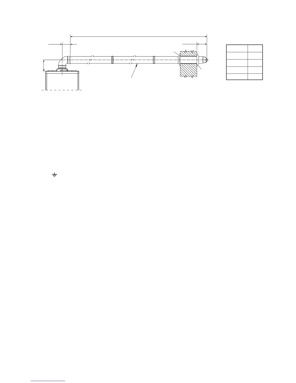
Fig. 4.10
Pro Tec 50
Pro Tec 70
Pro Tec 90
Pro Tec 115
14.5 m
11 m
8 m
5 m
L Max.
200 mm
136 mm
L Max.
180 mm
Inner seal