Do you have a question about the Alpine 7390M and is the answer not in the manual?
Specifies performance characteristics for FM reception.
Lists performance metrics for Medium Wave radio reception.
Details performance specifications for Long Wave radio reception.
Outlines technical specifications for the cassette tape playback function.
Details power requirements, unit dimensions, weight, and semiconductor count.
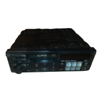
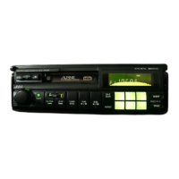
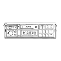
Introduces the Alpine 7390M and its integrated functions.
Addresses problems during initial power-up and basic unit functions.
Details troubleshooting steps for sound output and CD player faults.
Covers problems related to radio reception and tuning, including antenna.
Lists common problems encountered during tape playback and operation.
Explains error codes displayed for the CD changer unit and their resolution.
Highlights chassis, tape head, bracket, and full logic deck.
Describes preset, memory, DAP, Dolby NR, and audio outputs.
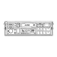
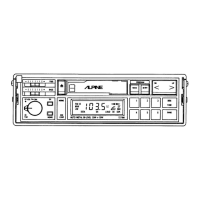
Illustrates the placement and numbering of all front panel controls.
Provides a list of error codes for the CD changer and their resolution.
Details the connections for power, audio outputs, and control signals.
Explains connections for inputs, outputs, dimmer, and audio interrupt.
Advises on fuse replacement, temperature limits, and handling practices.
Provides a detailed list of all controls and indicators with their respective numbers.
Covers power, volume, balance, fader, bass/treble, and loudness controls.
Explains how to switch modes and operate the radio functions.
Details FM stereo, manual tuning, auto seek, and memory preset procedures.
Covers Dolby, playback, pause, fast forward/rewind, and music sensor operations.
Explains CD playback, display switching, music sensor, and random play.
Guides on removing the front panel and the cassette deck mechanism.
Details steps for removing the bottom cover and the main PCB.
Outlines procedures for head azimuth, Dolby level, and tape speed adjustments.
Lists and describes the terminals for IC CXA1098Q.
Details the terminals for integrated circuit LC7582.
Lists and describes the terminals for IC 94468F04.
Provides terminal descriptions for IC 15590W07.
Continues terminal descriptions for IC 15590W07.
Provides the circuit diagram for the tuner section of the unit.
Illustrates the functional blocks and signal flow of the unit.
Presents the first part of the unit's detailed electronic schematic.
Continues the first section of the electronic schematic diagram.
Presents the second part of the unit's detailed electronic schematic.
Continues the second section of the electronic schematic diagram.
Continues the second section of the electronic schematic diagram.
Presents the third part of the unit's detailed electronic schematic.
Lists electronic components including ICs, transistors, and diodes.
Continues listing electronic components, focusing on diodes and capacitors.
Lists various capacitor types and their specifications.
Lists resistor values and part numbers.
Continues the list of resistor values and part numbers.
Lists resistors, ICs, transistors, diodes, LEDs, and switches.
Lists switches, lamps, and capacitors used in the unit.
Lists capacitors, resistors, GR control board parts, and miscellaneous items.
Provides a visual breakdown of the unit's cabinet and its components.
Lists all parts used in the assembly of the unit's cabinet.
Shows pin configurations for integrated circuits.
Continues pin configuration details for integrated circuits.
Provides pin configuration details for additional integrated circuits.
Lists pin configurations for various integrated circuits.
Shows pin configurations for further integrated circuits.
Details pin configurations for additional integrated circuits.
Illustrates pin configurations for transistors.
Continues pin configuration details for transistors.
Lists specific lock washer types, sizes, part numbers, and quantities.
Specifies the types of lubricants recommended for use.
Identifies specialized tools or jigs required for service.
Guides on removing and reattaching the unit's bottom cover.
Continues bottom cover reassembly and details eject operation procedures.
Details the replacement process for the eject gear and RF solenoid.
Guides on replacing the photo sensor and detector switch components.
Explains procedures for replacing the drive belt and the motor unit.
Details replacing flywheels, play solenoid, and eject solenoid.
Guides on replacing various gears including reverse idler, sun, and fixing gears.
Details replacing reverse lever, pause gear, and take-up gear assemblies.
Guides on replacing audio and control PC boards.
Details disassembly of cassette holder and replacement of reels.
Guides on replacing pinch rollers and the read/write head.
Explains the procedure for adjusting the head height using gauges.
Lists all parts for the cassette deck mechanism assembly.
Lists miscellaneous components like heads, motors, sensors, and solenoids.
| Type | Cassette Player |
|---|---|
| Brand | Alpine |
| Model | 7390M |
| DIN Size | 1 DIN |
| Channels | 2 |