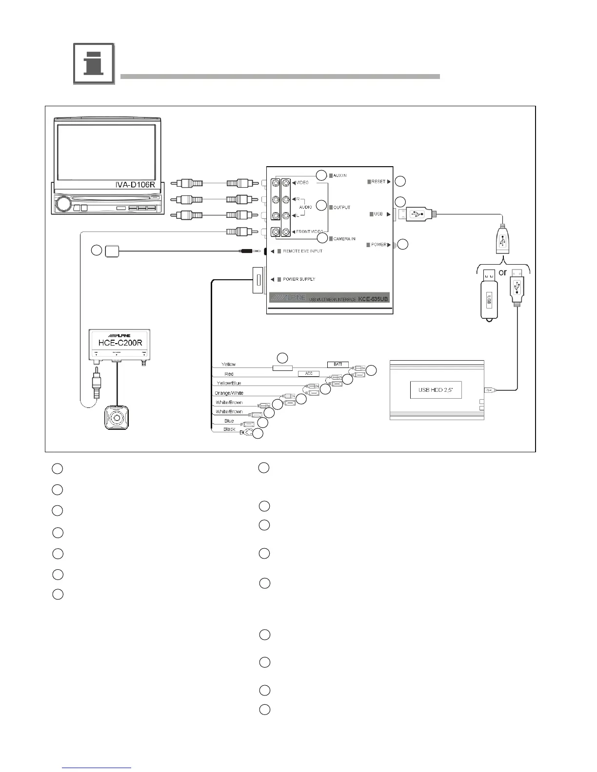
Connections and System Wiring Diagram
1
2
3
8
9
10
11
12
13
14
Reset button
USB socket
Power status LED
1x RCA A/V auxiliary input
1x RCA A/V output & front video output
Camera input
External IR sensor (optional)
Battery lead (yellow)
Connect to a live terminal in the fuse block connecting to the car
battery (bypassing the ignition switch).
Fuse holder (5A)
Switched power lead (Ignition) (red)
Connect to an accessory terminal in the fuse block.
Parking brake lead (yellow/blue)
Connect to vehicle’s parking brake lead of the car.
Reverse Lead (orange/white)
Use when connecting a rear view camera.
Connect to a Reverse gear activated 12 volt signal.
The camera signal is switched to the front video output only.
Remote control input lead (white/brown, male connector)
Connect to remote control output lead of monitor.
Remote control output lead (white/brown, female connector)
Connect to remote control input lead of auxiliary source device.
Remote Turn-on lead (blue)
Ground lead (black)
Connect to metallic body or chassis of the car.
12-EN
1
2
3
4
5
6
7
8
9
10
11
12
13
14
15
16
15
16
4
5
6
7
Installation and Connections
(not included)
(not included)
(not included)
(not included)
(not included)