Guideline: Clock Switchover
Use the following guidelines to design with clock switchover in PLLs:
• Clock loss detection and automatic clock switchover requires that the frequency difference between
inclk0 and inclk1 is within 20% range. Failing to meet this requirement causes the clkbad[0] and
clkbad[1] signals to function improperly.
• When using manual clock switchover, the frequency difference between inclk0 and inclk1 can be
more than 20%. However, differences between the two clock sources (frequency, phase, or both) can
cause the PLL to lose lock. Resetting the PLL ensures that the correct phase relationships are
maintained between the input and output clocks.
• Both inclk0 and inclk1 must be running when the clkswitch signal goes high to start the manual
clock switchover event. Failing to meet this requirement causes the clock switchover to malfunction.
• Applications that require a clock switchover feature and a small frequency drift must use a low-
bandwidth PLL. When referencing input clock changes, the low-bandwidth PLL reacts slower than a
high-bandwidth PLL. When the switchover happens, the low-bandwidth PLL propagates the stoppage
of the clock to the output at a slower speed than the high-bandwidth PLL. The low-bandwidth PLL
filters out jitter on the reference clock. However, be aware that the low-bandwidth PLL also increases
lock time.
• After a switchover occurs, there might be a finite resynchronization period for the PLL to lock onto a
new clock. The exact amount of time it takes for the PLL to relock depends on the PLL configuration.
• The phase relationship between the input clock to the PLL and output clock from the PLL is important
in your design. Assert areset for 10 ns after performing a clock switchover. Wait for the locked signal
(or gated lock) to go high before reenabling the output clocks from the PLL.
• Disable the system during switchover if the system is not tolerant of frequency variations during the
PLL resynchronization period. You can use the clkbad[0] and clkbad[1] status signals to turn off the
PFD (pfdena = 0) so that the VCO maintains its last frequency. You can also use the switchover state
machine to switch over to the secondary clock. After enabling the PFD, the output clock enable signals
(clkena) can disable clock outputs during the switchover and resynchronization period. After the lock
indication is stable, the system can reenable the output clock or clocks.
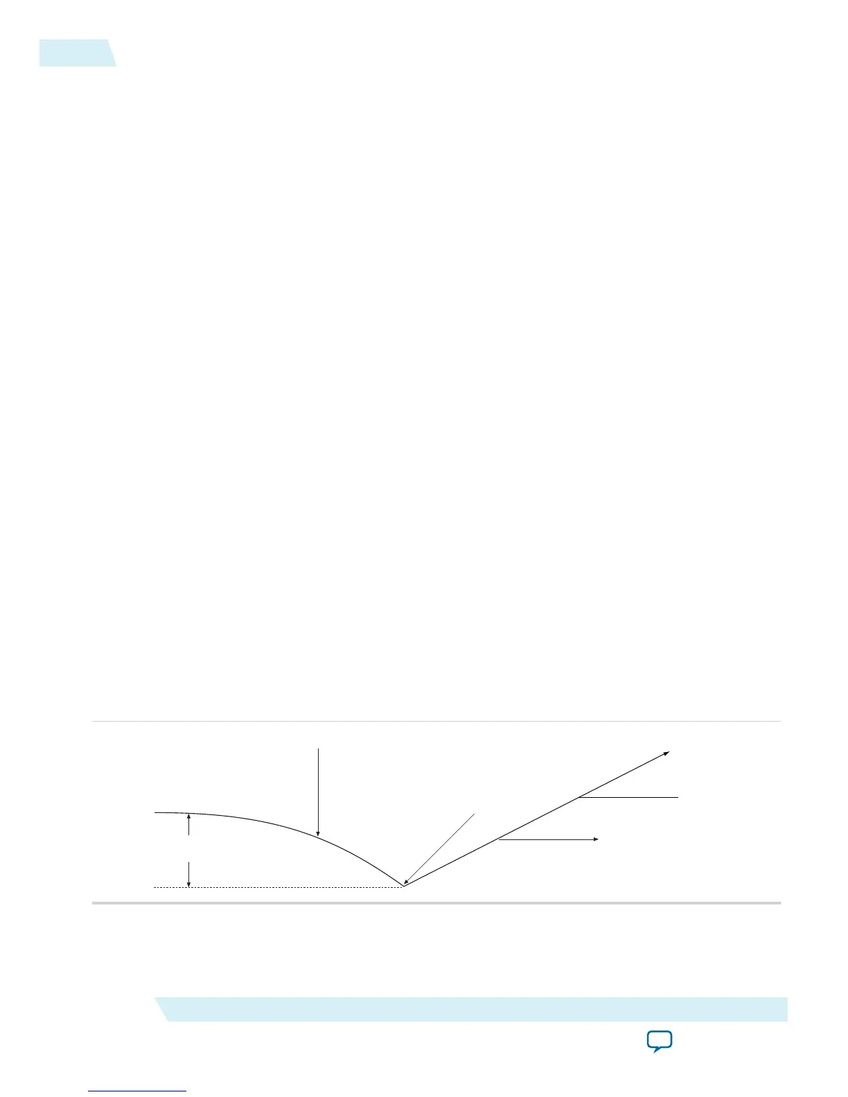
• The VCO frequency gradually decreases when the primary clock is lost and then increases as the VCO
locks onto the secondary clock, as shown in the following figure. After the VCO locks onto the
secondary clock, some overshoot can occur (an over-frequency condition) in the VCO frequency.
Figure 3-1: VCO Switchover Operating Frequency
ΔF
vco
Primary Clock Stops Running
Switchover Occurs
VCO Tracks Secondary Clock
Frequency Overshoot
Related Information
• Clock Switchover on page 2-22
3-4
Guideline: Clock Switchover
UG-M10CLKPLL
2015.06.12
Altera Corporation
MAX 10 Clocking and PLL Design Considerations
Send Feedback