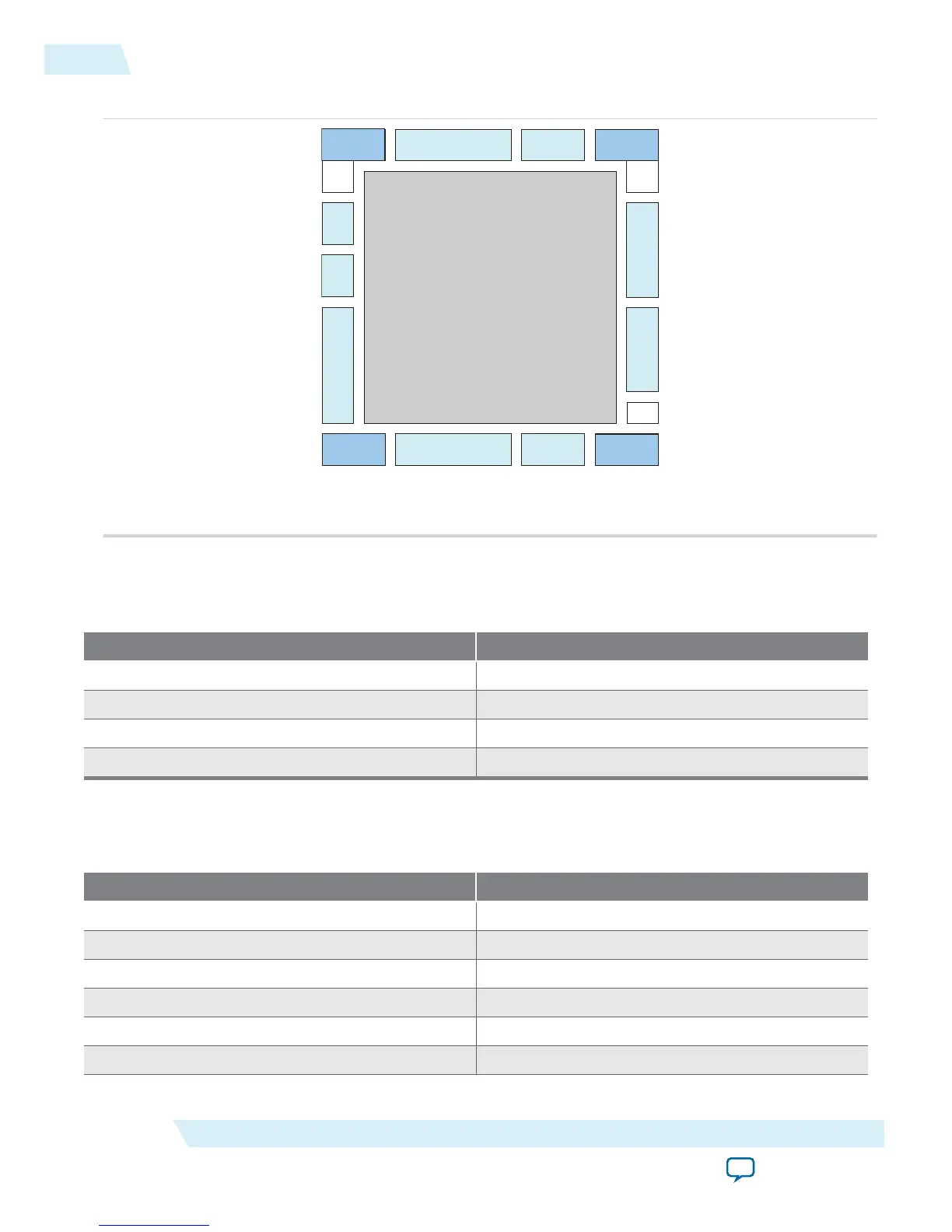
Figure 2-10: PLL Locations for 10M16, 10M25, 10M40 and 10M50 Devices
Bank 8
Bank 1A
Bank 2
Bank 6Bank 5
PLL 1
PLL 2 (1)Bank 7
Bank 3 Bank 4
Bank 1B
PLL 3 (1)
PLL 4 (1)
OCT
Note:
(1) Available on all packages except E144 and U169 packages.
Clock Pin to PLL Connections
Table 2-5: MAX 10 Dedicated Clock Input Pin Connectivity to PLL
Dedicated Clock Pin PLL
CLK[0,1][p,n] PLL1, PLL3
CLK[2,3][p,n] PLL2, PLL4
CLK[4,5][p,n] PLL2, PLL3
CLK[6,7][p,n] PLL1, PLL4
PLL Counter to GCLK Connections
Table 2-6: MAX 10 PLL Counter Connectivity to the GCLK Networks
PLL Counter Output GCLK
PLL1_C0 GCLK[0,3,15,18]
PLL1_C1 GCLK[1,4,16,19]
PLL1_C2 GCLK[0,2,15,17]
PLL1_C3 GCLK[1,3,16,18]
PLL1_C4 GCLK[2,4,17,19]
PLL2_C0 GCLK[5,8,10,13]
2-12
Clock Pin to PLL Connections
UG-M10CLKPLL
2015.06.12
Altera Corporation
MAX 10 Clocking and PLL Architecture and Features
Send Feedback