50 EAV64301 01/2015
Sink / Source Switch Configuration
The switch is used to adapt the operation of the logic inputs to the technology of the programmable
controller outputs. To access the switch, follow the Acess to control Terminals procedure (seepage90).
The switch is located below the control terminals (see page 89).
z Set the switch to Source (factory setting) if using PLC outputs with PNP transistors.
z Set the switch to Ext if using PLC outputs with NPN transistors.
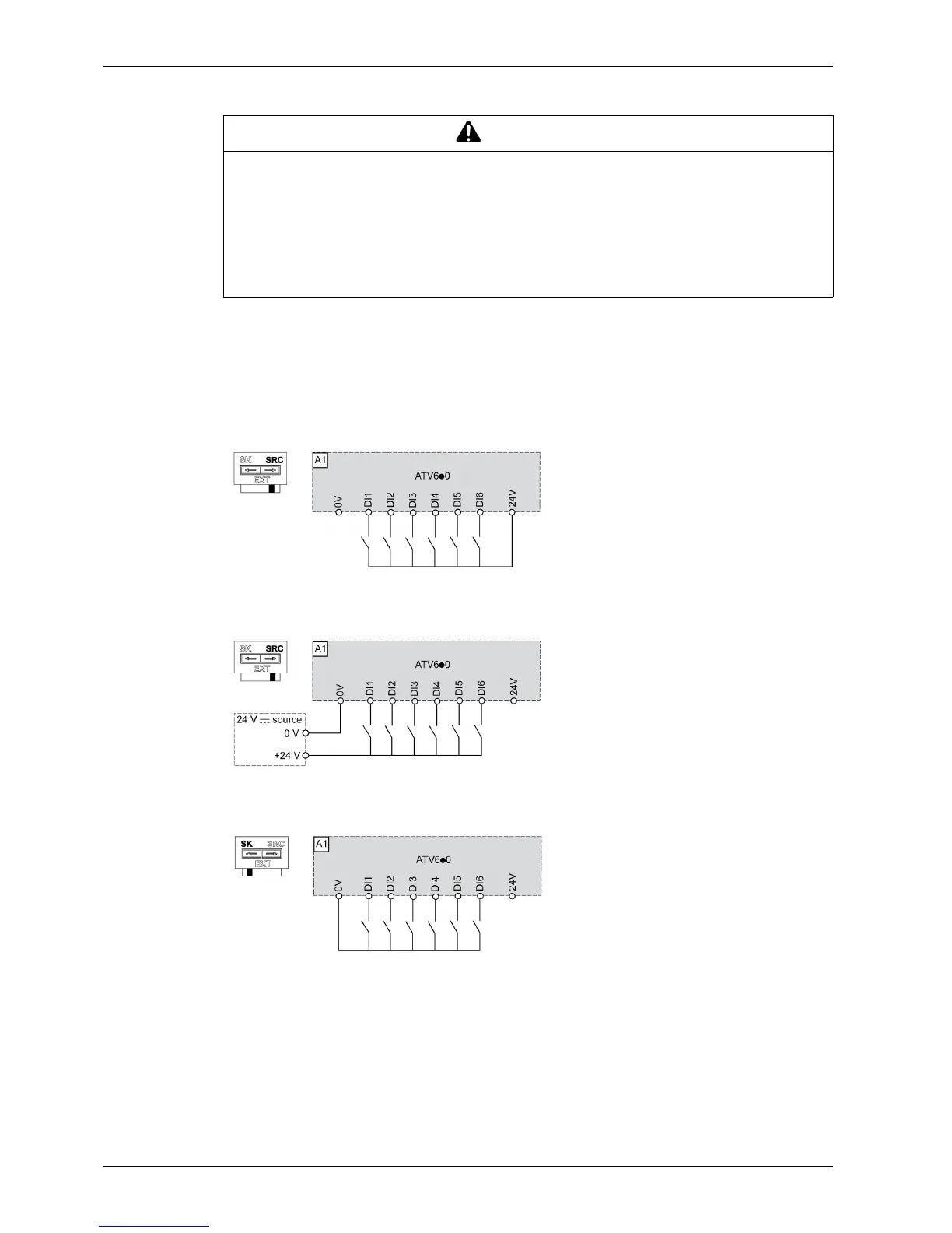
Switch Set to SRC (Source) Position Using the Output Power Supply for the Digital Inputs
Switch Set to SRC (Source) Position and Use of an External Power Supply for the DIs
Switch Set to SK (Sink) Position Using the Output Power Supply for the Digital Inputs
WARNING
UNANTICIPATED EQUIPMENT OPERATION
z If the drive is set to Sink Int or Sink Ext, do not connect the 0 V terminal to ground or to protective
ground.
z Verify that accidental grounding of digital inputs configured for sink logic, caused, for example, by
damage to the signal cables, cannot occur.
z Follow all applicable standards and directives such as NFPA 79 and EN 60204 for proper control
circuit grounding practices.
Failure to follow these instructions can result in death, serious injury, or equipment damage.