90 EAV64301 01/2015
Wiring The Control Part
Preliminary Steps
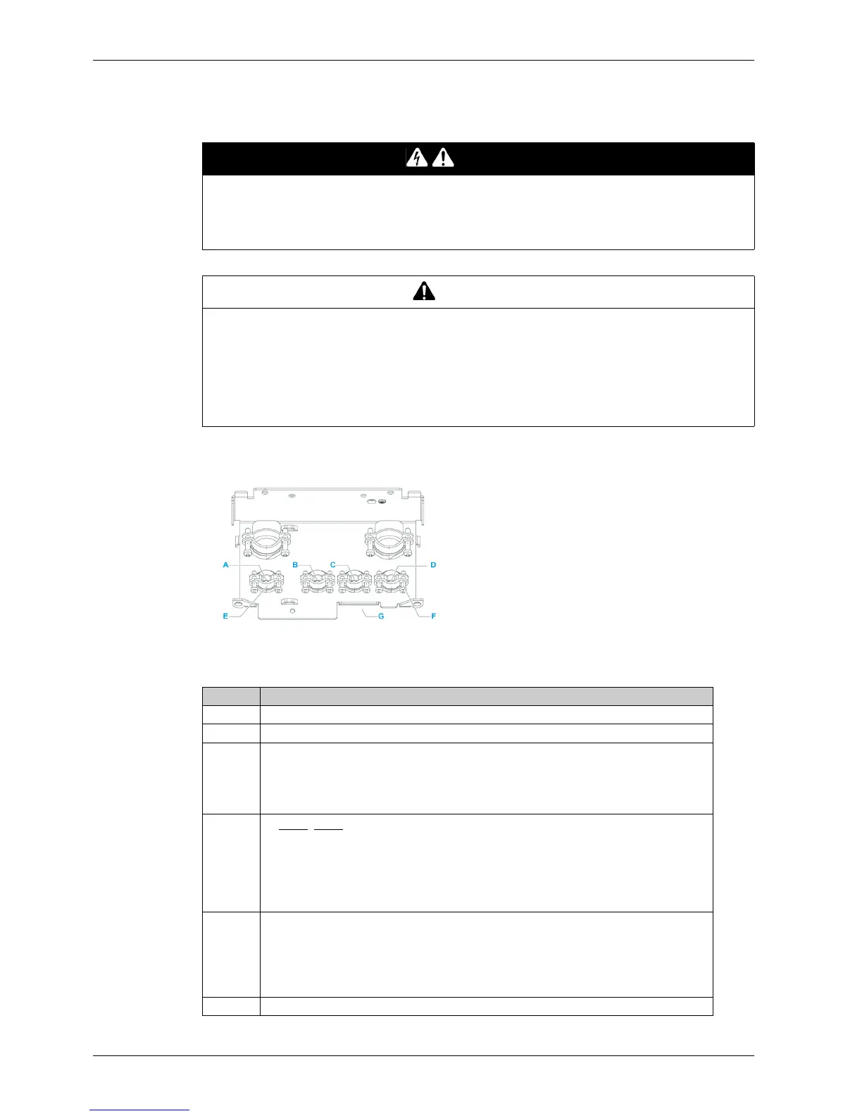
Cabling plate preparation
NOTE: Cabling plate shown is for frame size 3. Other cabling plates look slightly differs from this one.
Apply the following instructions before connecting the control cables to the drive
DANGER
HAZARD OF ELECTRIC SHOCK, EXPLOSION OR ARC FLASH
Read and understand the instructions in Safety Information chapter before performing any procedure
in this chapter.
Failure to follow these instructions will result in death or serious injury.
WARNING
UNINTENDED BEHAVIOR OF INPUTS AND OUTPUTS
The functions of the inputs and outputs depend on the selected operating mode and the settings of the
corresponding parameters.
z Verify that the wiring is appropriate for the settings.
z Only start the system if there are no persons or obstructions in the hazardous area.
z When commissioning, carefully run tests for all operating states and potential error situations.
Failure to follow these instructions can result in death, serious injury, or equipment damage.
Step Action
1 Unscrew the cable grommet (E) screws (D) if required
2 Insert in drilling (A) and (B) the option cables, such as communication modules.
3 Insert in drilling (C) the cable including the wires for the following terminals
z P24
z 0V
z DI1...DI6
z 24V
4 Insert in drilling (D) the cable including the wires for the following terminals
z STOA, STOB
z 24V
z COM
z AO1, AO2
z 10 V
z AI1...AI3
5 Location G is intended to receive the wires for the following terminals
z R1A...R1C
z R2A...R2C
z R3A...R3C
z RJ45
z Other options
6 Screw back the cable grommet screws