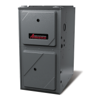
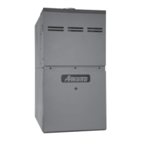
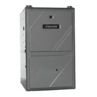
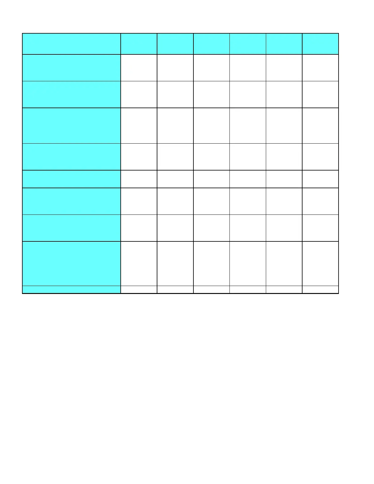
FURNACE SPECIFICATIONS
8 Rev. 1
1. These furnaces are manufactured for natural gas operation. Optional kits are available for conversion to propane opera-
tion.
2. For elevations above 2000 ft. the rating should be reduced by 4% for each 1000 ft. above sea level. The furnace must not
be derated, orifice changes should only be made if necessary for altitude.
3. The total heat loss from the structure as expressed in TOTAL BTU/HR must be calculated by the manufacturers
method or in accordance with the "A.S.H.R.A.E. GUIDE" or "MANUAL J-LOAD CALCULATIONS" published by the AIR
CONDITIONING CONTRACTORS OF AMERICA. The total heat loss calculated should be equal to or less than the
heating capacity. Output based on D.O.E. test procedures, steady state efficiency times output.
4. Minimum Circuit Ampacity calculated as: (1.25 x Circulator Blower Amps) + I.D. Blower Amps.
MODEL
GUID045CA30
GUID045CX30
GUID045DA30
GUID045DX30
GUID070CA30
GUID070CX30
GUID070DA30
GUID070DX30
GUID070CA40
GUID070CX40
GUID070DA40
GUID070DX40
GUID090CA30
GUID090CX30
GUID090DA30
GUID090CA50
GUID090CX50
GUID090DA50
GUID090DX50
GUID115CA50
GUID115CX50
GUID115DA50
GUID115DX50
Btuh Input (US)
46,000 69,000 69,000 92,000 92,000 115,000
Output (US)
36,800 55,200 55,200 73,600 73,600 92,000
A.F.U.E.
80% 80% 80% 80% 80% 80%
Rated External Static (" w.c.)
.10 - .50 .12 - .50 .12 - .50 .15 - .50 .15 - .50 .20 - .50
Temperature Rise (°F)
35 - 65 35 - 65 35 - 65 40 - 70 40 - 70 40 - 70
Pressure Switch Trip Point (" w.c.)
-0.55 -0.55 -0.55 -0.55 -0.55 -0.55
Blower Wheel (D" x W")
9 x 8 9 x 8 10 x 6 10 x 8 10 x 8 10 x 9
Blower Horsepower
1/3 1/3 1/2 1/2 3/4 3/4
Blower Speeds
444444
Max CFM @ 0.5 E.S.P.
1200 1290 1529 1380 1975 1985
Power Supply
115-60-1 115-60-1 115-60-1 115-60-1 115-60-1 115-60-1
Minimum Circuit Ampacity (MCA)
8.6 8.5 10.4 8.2 14.6 13.1
Maximum Overcurrent Device
15 15 15 15 15 15
Transformer (VA)
40 40 40 40 40 40
Heat Anticipator
0.7 0.7 0.7 0.7 0.7 0.7
Primary Limit Setting (°F)
230 220 170 *150 160 190
Auxiliary Limit Setting (°F)
160 160 160 160 160 160
Rollout Limit Setting (°F)
250 300 300 300 300 275
Fan Delay On
30 secs. 30 secs. 30 secs. 30 secs. 30 secs. 30 secs.
Off Heating *
90 secs. 90 secs. 90 secs. 90 secs. 90 secs. 90 secs.
Off Cooling
45 secs. 45 secs. 45 secs. 45 secs. 45 secs. 45 secs.
Gas Supply Pressure (Natural/Propane) ("w.c.)
11-Jul 11-Jul 11-Jul 11-Jul 11-Jul 11-Jul
Manifold Pressure (Natural/Propane) ("w.c.)
3.5 / 10 3.5 / 10 3.5 / 10 3.5 / 10 3.5 / 10 3.5 / 10
Orifice Size (Natural/Propane)
#43 / #55 #43 / #55 #43 / #55 #43 / #55 #43 / #55 #43 / #55
Number of Burners
233445
Vent Connector Diameter (inches)
444444
Shipping Weight (lbs.)
140 151 152 169 178 194
*150 = The GUID090**30 furnaces were changed from primary limit part #10728331 (160°F) to limit part #10728332 (150°F) per ECN60850 effective June 6, 2000.
* Off Heating - This fan delay timing is adjustable (60, 90, 120 or 180 seconds), 90 seconds as shipped.
 Loading...