Do you have a question about the Amana 40" and is the answer not in the manual?
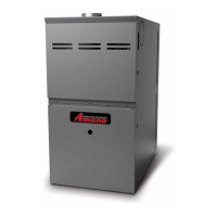
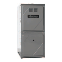
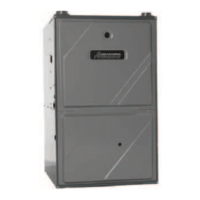
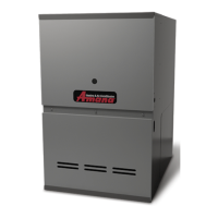
Specifies the model series and type of gas furnaces covered by this manual.
Indicates where to find model and manufacturing numbers for identification.
Details the alphanumeric structure and meaning of furnace model number segments.
Lists furnace input ratings and corresponding airflow capacities (tons).
Explains the electronic ignition, induced draft blower, and self-diagnosing control.
Specifies minimum clearances required around the furnace for safety and maintenance.
Details the need for specific kits and adjustments for high-altitude installations.
Provides guidance on furnace placement and installation environment requirements.
Table showing the specific dimensions (A, B, C, D, E) for various GUID furnace models.
Provides data on pressure switch settings for furnace operation and safety.
Summarizes settings for primary, rollout, and auxiliary limit switches.
Table matching furnace models with appropriate cased and uncased Amana coils.
Recommends specific Amana thermostat models for use with the furnace.
Table listing key parameters like input/output, AFUE, static pressure, and speeds.
Charts showing blower airflow (CFM) at different external static pressure levels.
Visualizes the relationship between BTU output, CFM, and temperature rise.
Detailed schematic of the furnace's electrical control and power circuits.
Shows factory-wired connections between the blower motor and the control board.
Wiring schematic for the HSI 1-1A integrated ignition control system.
Wiring schematic for the HSI-2 integrated ignition control system.
Wiring schematic for the WR50A55 integrated ignition control system.