EasyManua.ls Logo

Amana ASPT61D14 Series - User Manual

Amana ASPT61D14 Series
24 pages
Print Icon
To Next Page IconTo Next Page
Loading...
RECOGNIZE THIS SYMBOL
AS A SAFETY PRECAUTION.
ATTENTION INSTALLING PERSONNEL
Prior to installation, thoroughly familiarize yourself with this Installation Manual.
Observe all safety warnings. During installation or repair, caution is to be observed.
It is your responsibility to install the product safely and to educate the customer on its safe use.
ARUF**14** / ASPT**14**
1 Important Safety Instructions
The following symbols and labels are used throughout this
manual to indicate immediate or potential safety hazards.
It is the owner’s and installer’s responsibility to read and
comply with all safety information and instructions accom-
panying these symbols. Failure to heed safety information
increases the risk of personal injury, property damage, and/
or product damage.
AIR HANDLERS INSTALLATION & OPERATING INSTRUCTIONS
IO-901
2/2015
Keep this literature in a safe place for future reference.
1 Important Safety Instructions...................................1
2 Shipping Inspection ............................................... 3
2.1 Parts .......................................................... 3
2.2 Handling ...................................................... 3
3 Codes & Regulations ..............................................3
4 Replacement Parts ................................................3
5 Pre-Installation Considerations ................................ 3
5.1 Preparation .................................................. 3
5.2 System Matches ............................................. 3
5.3 Interconnecting Tubing..................................... 3
5.4 Clearances ................................................... 4
5.5 Horizontal Applications .................................... 4
6 Installation Location .............................................4
6.1 Upflow Installation ......................................... 4
6.2 Horizontal Left Installation ............................... 4
6.3 Downflow..................................................... 4
6.4 Horizontal Right Installation.............................. 5
7 Refrigerant Lines .................................................. 7
7.1 Tubing Size ................................................... 7
7.2 Tubing Preparation ......................................... 7
7.3 Special Instructions......................................... 7
7.4 Tubing Connections for Flowrator Model ............... 7
7.5 Tubing Connections for TXV Models ...................... 8
8 Condensate Drain Lines .......................................... 8
9 Ductwork............................................................ 9
9.1 Return Ductwork ............................................ 9
10 Return Air Filters ................................................9
11 Electric Heat......................................................9
12 Electrical and Control Wiring ............................... 11
12.1 Building Electrical Service Inspection................ 11
12.2 Wire Sizing ............................................... 11
12.3 Maximum Overcurrent Protection (MOP) ............ 11
12.4 Electrical Connections – Supply Voltage ............. 12
12.4.1 Air Handler Only (Non-Heat Kit Models) ..... 12
12.4.2 Air Handler - Non-Circuit Breaker Heat Kits......12
12.4.3 Air Handler With Circuit Breaker Heat Kit........ 12
12.5 Low Voltage Connections............................... 12
12.5.1 Thermostats .......................................... 12
12.6 Speed Tap Adjustment .................................. 12
13 Achieving 1.4% Low Leakage Rate ......................... 13
14 Start-Up Procedure............................................ 13
15 Regular Maintenance.......................................... 13
16 Airflow Data .................................................... 14
21 Wiring Diagrams................................................ 20
Contents
Question and Answer IconNeed help?

Do you have a question about the Amana ASPT61D14 Series and is the answer not in the manual?

Summary

Important Safety Instructions

Attention Installing Personnel

Instructions for installers to familiarize themselves with the manual and observe safety warnings during installation or repair.

Safety Warnings and Precautions

High Voltage Warning

Warning about high voltage, advising to disconnect power before servicing to prevent injury or death.

Technician Qualification Warning

Stipulates that installation and repair should only be performed by qualified technicians.

Electrical Ground Warning

Emphasizes the necessity of an uninterrupted electrical ground for safety and to prevent shock.

Non-Approved Devices Warning

Warns against using non-certified devices, which can cause damage, injury, or poor performance.

Combustible Materials Warning

Advises against storing flammable materials or using gasoline near the unit to prevent risk of damage or injury.

Carbon Monoxide Poisoning Hazard

Warns about carbon monoxide poisoning from devices in enclosed areas and the need for adequate ventilation.

Codes and Regulations Compliance

National and Local Codes

States that installation must comply with applicable national, local, and state codes and regulations.

Pre-Installation Considerations

Preparation Steps

Instructions to read all instructions, understand procedures, and gather necessary tools and supplies.

System Match Requirements

Mandates manufacturer-approved and AHRI-listed system matches to avoid voiding the warranty.

Installation Clearances

Service Clearance Requirements

Specifies minimum clearances for combustible surfaces and service access, including electrical wiring.

Installation Location and Orientations

Indoor Installation Only

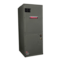
Specifies that these air handlers are designed exclusively for indoor installation.

Unit Orientations

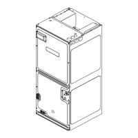
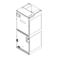
Details the available installation orientations: upflow, downflow, horizontal left, and horizontal right.

Downflow Installation

Recommends a downflow kit (DFK) for downflow applications to prevent coil pan sweating.

Horizontal Right Installation Procedure

Component Removal

Instructions for removing access panels, coil assembly, and center support for horizontal right orientation.

Coil Assembly Re-installation

Details on sliding the coil assembly back into the cabinet on downflow brackets.

Refrigerant Line Installation

Special Instructions for Brazing

Recommends quenching cloths for brazing, using 5% silver alloy, and appropriate heat levels.

Tubing Connections for Flowrator Models

Expelling Tracer Gas

Procedure to loosen the nut to allow tracer gas to escape, checking for leaks.

Final Flowrator Tubing Connections

Tubing Connections for TXV Models

Condensate Drain Line Installation

Condensate Trap Requirement

Mandates a 'P' style trap close to the evaporator coil for proper drainage, as per codes.

Ductwork Installation and Sizing

Ductwork System Requirements

Specifies the need for a complete supply and return ductwork system sized for 350-450 CFM per ton.

Return Air Filter Installation

Electric Heat Kit CFM Requirements

Electrical and Control Wiring

Wire Sizing Guidelines

Provides guidelines for wire sizing, including MCA, voltage drop, NEC/CSA codes, and insulation ratings.

Maximum Overcurrent Protection (MOP)

Details requirements for approved overcurrent protection devices, sizing relative to MCA and MOP.

Electrical Connections and Supply Voltage

Low Voltage Connections

Thermostat Wiring

Details low voltage wiring for thermostats, explaining connections for single/multi-stage cooling and heat pump.

Achieving 1.4% Low Airflow Leakage

Start-Up Procedure Checklist

Pre-Start Up Checks

Checklist for ensuring electrical wires, panels, tubing, condensate lines, and low voltage wiring are correct.

Regular Maintenance

User Maintenance

Specifies that the circulating air filter is the only user-maintainable item, requiring monthly cleaning/replacement.

Air Handler Low Voltage Connections

Wiring Diagram Configurations

Details various wiring configurations for single-stage cooling, heat pump, and electric heating applications.

Cooling Unit Wiring Diagrams

Heat Pump Unit Wiring

Wiring diagram for heat pump units with optional heat kits (10 kW and below).

Heat Pump Unit with Optional Heat Kits Wiring

ARUF**14** Wiring Diagrams

ARUF**14** High Voltage Wiring

Diagram for ARUF**14** showing high voltage power supply, terminal block, and motor connections.

ARUF**14** Low Voltage Wiring

Diagram for ARUF**14** illustrating low voltage connections to thermostat, transformer, and relays.

ASPT**14** Wiring Diagrams

ASPT**14** High Voltage Wiring

Diagram for ASPT**14** showing high voltage power supply, ground, and external connections.

ASPT**14** Low Voltage Wiring

Diagram for ASPT**14** showing low voltage connections to thermostat, transformer, and optional relays.

3-Phase Heat Kit Installation

3-Phase Heat Kit Wiring Diagram

Wiring diagram for a 3-phase heat kit, showing connections for circuits, transformer, and components.

Split Systems Maintenance Recommendations

Indoor Air Filter Maintenance

Emphasizes never operating without a filter and checking/replacing it monthly.

Amana ASPT61D14 Series Specifications

General IconGeneral
BrandAmana
ModelASPT61D14 Series
CategoryAir Handlers
LanguageEnglish

Related product manuals