TROUBLESHOOTING
12
A
VOID
CONTACT
WITH
THE
CHARGED
AREA
.
•N
EVER
TOUCH
THE
CHARGED
AREA
BEFORE
CONFIRMING
THAT
THE
RESIDUAL
VOLTAGE
IS
50
VOLTS
OR
LESS
.
1. S
HUT
DOWN
THE
POWER
AND
LEAVE
THE
CONTROL
BOX
FOR
10
MINUTES
.
2. M
AKE
SURE
TO
TOUCH
THE
E
ARTH
GROUND
TERMINAL
TO
RELEASE
THE
STATIC
ELECTRICITY
FROM
YOUR
BODY
(
TO
PREVENT
FAILURE
OF
THE
PC
BOARD
).
3. M
EASURE
THE
RESIDUAL
VOLTAGE
IN
THE
SPECIFIED
MEASUREMENT
POSITION
USING
A
VOM
WHILE
PAYING
ATTENTION
NOT
TO
TOUCH
THE
CHARGED
AREA
.
4. I
MMEDIATELY
AFTER
MEASURING
THE
RESIDUAL
VOLTAGE
,
DISCONNECT
THE
CONNECTORS
OF
THE
OUTDOOR
UNIT
’
S
FAN
MOTOR
. (I
F
THE
FAN
BLADE
ROTATES
BY
STRONG
WIND
BLOWING
AGAINST
IT
,
THE
CAPACITOR
WILL BE CHARGED,
CAUSING
THE
DANGER
OF
ELECTRICAL
SHOCK
.)
WARNING
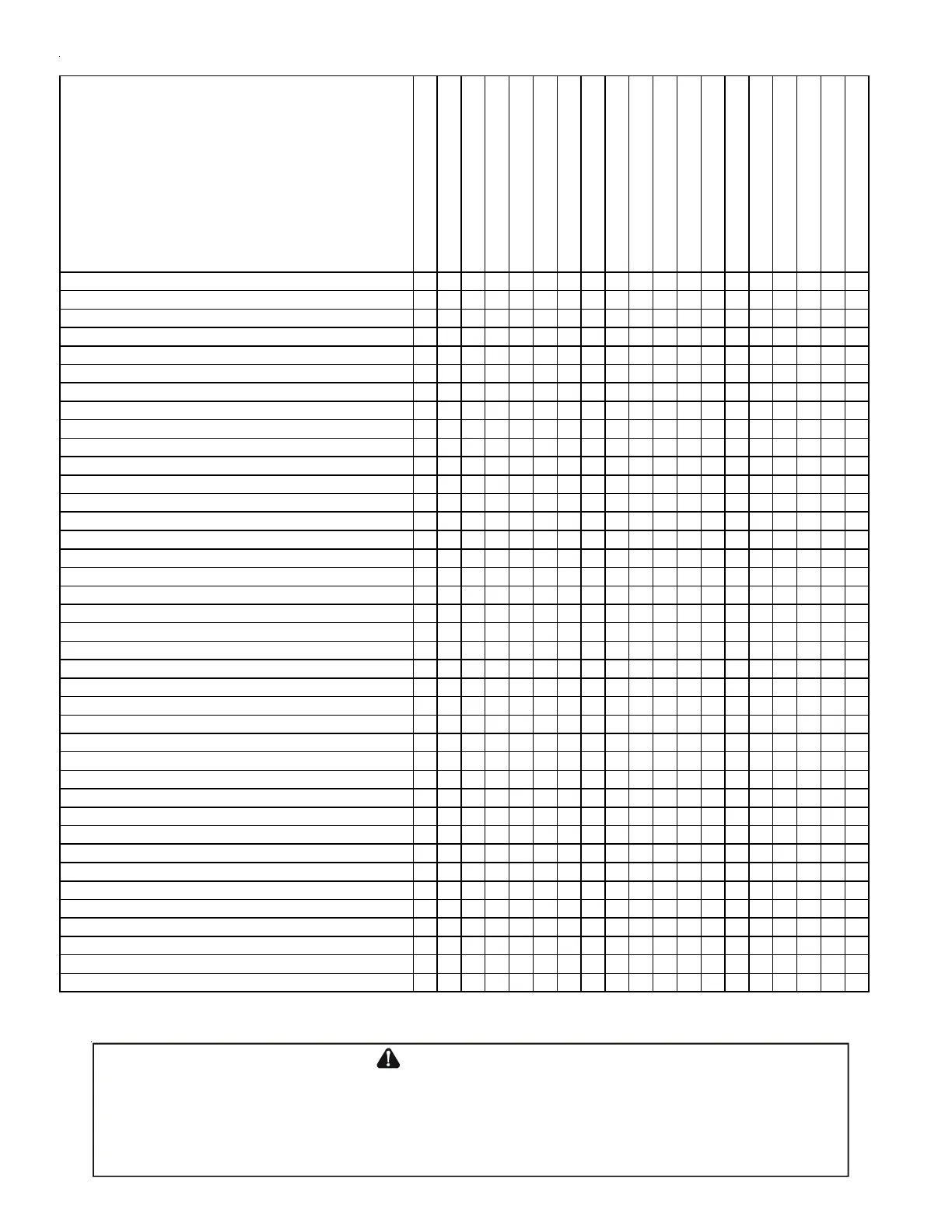
POSSIBLE CAUSE
X IN ANALYSIS GUIDE INDICATE
"POSSIBLE CAUSE"
Comp discharge temp > 200F
Comp discharge temp < 105F
Comp discharge SH > 70F
Comp discharge SH < 20F
High pressure > 490psi
High pressure SSV< 270psi
High pressure LSV< 270psi
LSV SC > 12F
LSV SC < 4F
Low pressure < 40psi
Requested % demand < Actual %
Requested % demand > Actual %
Repeated stop/start
Weak heating
No switch heating
Noise
Incomplete defrost operation
Stop operation
Sweating liquid line
Liquid stop valve does not fully open
XXX XXXXX XX
Gas stop valve does not fully open
XXX XXXXX X
Line set restriction
XXX XXXXX XX
Line set length is too long
XX X
Blocked filter-dryer
XXX XXXXX XX
OD EEV coil failure
XXXXXXXXXXXXXX XX
OD EEV failure
XXXXXXXXXXXXXX XX
ID EEV coil failure
XXXXXXXXXX XXX
ID EEV failure
XXXXXXXXXX XXX
Check valve failure – Leakage
XX XXXX X
High Pressure switch failure
X
Pressure sensor failure
XXXXXXX XXXX X
Suction temp sensor failure
XXXX XXXXXXX X
Discharge temp sensor failure
XXXX XXXX X
Coil temp sensor failure
X XXX XX
Defrost sensor failure
X XXX XX
Liquid temp sensor failure
XX XX
Ambient temp sensor failure
XXXXXXX
OD recirculation
XX XX XXXX
ID recirculation
XXX XXX
Dirty OD Heat-exchanger
XX XX XXXX X
Dirty ID Heat-exchanger
XXX XXX
Outdoor Ambient temp is too high
XXXXXX
Outdoor Ambient temp is too low
XXX XXXXXXX
ID suction temp is too high
XX XXX
ID suction temp is too low
XX X
Mixture of non-condensible gas
XXX XXXXX
OD fan motor failure
XX XX XXXX X
RV failure
XXX XXXXXX
RV coil failure
XXX XXXX
Over charge
XXX X XXXX X
Under charge
XXX XX XX XX X
Leak
XXX XX XX XX X
ID failure
XXXXXXXXXXXXXX XXXX
OD Control Board failure
X
Compressor failure
XXXX XX XXX XXX
Cooling loop is not attached
XXX
Cooling loop grease is not enough
XXX
Low ID CFM
XXXXXXX
Indoor Normal Tem
erature O
eratin
Ran
e: 65-85°F
HEATING ANALYSIS CHART
Outdoor Normal Temperature Operating Range: 17-62°F
 Loading...