SYSTEM OPERATION
17
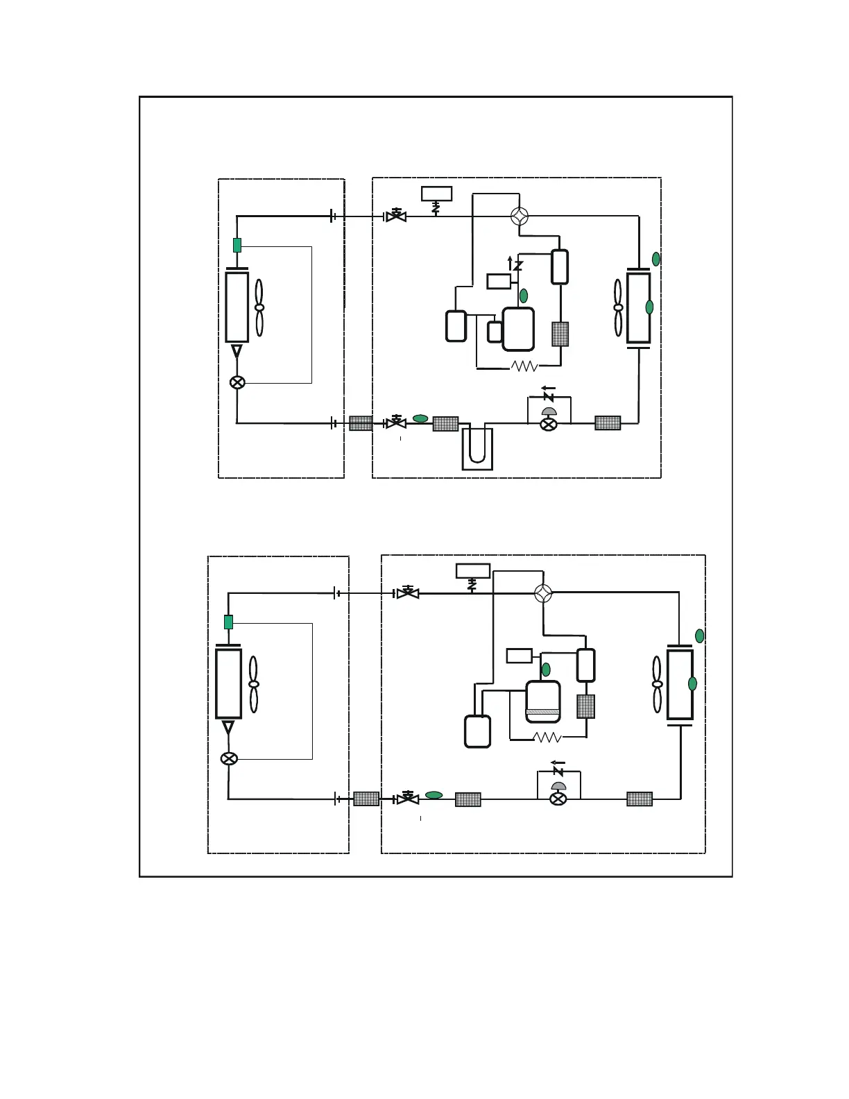
COOLING CYCLE
LEGEND:
Tl = Thermistor (Outdoor Liquid Temperature)
Td = Thermistor (Discharge Temperature)
Ta = Thermistor (Outdoor Air Temperature)
HP/LP sensor = High/Low Pressure Sensor
HPS = High Pressure Switch
Tm = Thermistor (Outdoor Coil Temperature)
Piping Diagram with TXV applicable indoor unit (2 - 4 Ton)
Hex
Fan
Motor
Td Thermistor
Filter
dryer
Stop
Va l v e
(Liquid)
Ball Valve
(Gas)
Fan
Motor
Hex
HP/LP
HP/LP sensor
Ta Thermistor
HPS
Outdoor unit
Indoor unit
TXV
Accumulator
Tm
Thermistor
T
Thermistor
Oil
separator
Filter
Compressor
Crankcase
heater
Capillary tube
Reversing
Va lv e
Filter
Filter
Check
valve
EEV
Hex
Fan
Motor
Filter
dryer
Stop
Va lv e
(Liquid)
Ball Valve
(Gas)
Fan
Motor
Hex
HP/LP
HP/LP sensor
Tm
Thermistor
Ref cooling
Ta Thermistor
Outdoor unit
Indoor unit
TXV
Check
valve
Td Thermistor
Filter
Compressor
Capillary tube
HPS
Oil
separator
Accumulator
T Thermistor
Reversing
Va l v e
Check
valve
EEV
Filter
Filter
Piping Diagram with TXV applicable indoor unit (5 Ton)
 Loading...