SERVICING
41
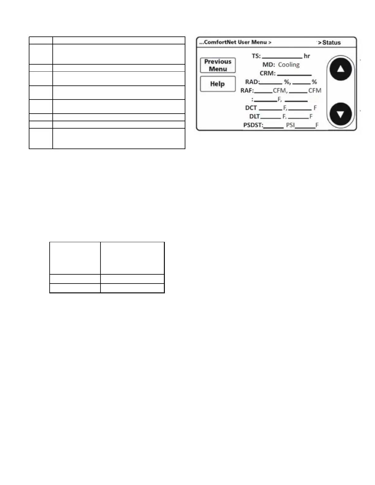
3. Follow screen for System Status.
TS Time Stamp (Compressor run time)
MD
Current system operational Mode
(cooling, cooling startup, heating, heating startup, oil
return
defrost
sto
CRM Compressor Reduction Mode
RAD
Requested and Actual percentage Demand
(Requested Demand, Actual cooling / heating provided)
RAF
Requested and Reported ID airflow
(Requested CFM, Actual CFM)
ATOF*
Outdoor Air Temperature, Outdoor Fan speed
(OD air temperature, OD Fan RPM)
DCT Discharge Temperature, Outdoor Coil Temperature
DLT Defrost sensor temperature, Outdoor Liquid Temperature
PSDST**
Pressure sensor reading
Suction Pressure (cooling mode)
Discharge pressure (heating mode)
* Only for AVZC20**1AB or later revision.
ATPRM is shown in AVZC20**1AA revision.
** Only for AVZC20**1AB or later revision.
PSD is shown in AVZC20**1AA revision.
Heat Pump With Outdoor Temperature Lockouts
It is recommended to set the outdoor temperature lockouts during
the initial thermostat set up. This will enable the compressor to
be turned off and switch heating source from refrigeration to aux-
iliary/secondary heating under low ambient conditions.
Line set length
range (feet)
Compressor lockout
temperature
(°F)
0 to 100 15
100 to 200 20
For example if the line set is 125 feet, it is recommended to set the
compressor lockout temperature at 20 °F during initial set up. In
order to access the compressor lockout temperature, Press MENU
and scroll down to press INSTALLER OPTIONS. Enter the date code
(password) when prompted. Choose VIEW / EDIT CURRENT SETUP
and COMPRESSOR LOCKOUT / BALANCE POINT will be under HEAT
/ COOL CONTROL OPTIONS. For more information please refer to
COMFORTNET™ CTK04 Communicating Thermostat SYSTEM INSTAL-
LATION GUIDE.
RPM
HEAT PUMP
 Loading...