BAG0014.4 09.14
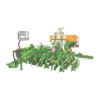
Two pins (Fig. 81/3 und Fig. 81/4) function as
stroke limiters for the stroke of the hydraulic ram
(Fig. 81/1) placed within the setting segment.
When the hydraulic ram is without pressure the
top of it rests on the pin (Fig. 81
hydraulic ram is pressurised it rests on the pin
(Fig. 81/4).
Setting the normal coulter pressure
Pressurise hydraulic ram (Fig. 81/1).
Insert the pin (Fig. 81/3) into one of the holes of
the quadrant plate and secure by using a clip pin
(Fig. 81/2).
Each hole of the quadrant plate is marked with a
figure. An increasing figure indicates an increase
in the coulter pressure (Fig. 83).
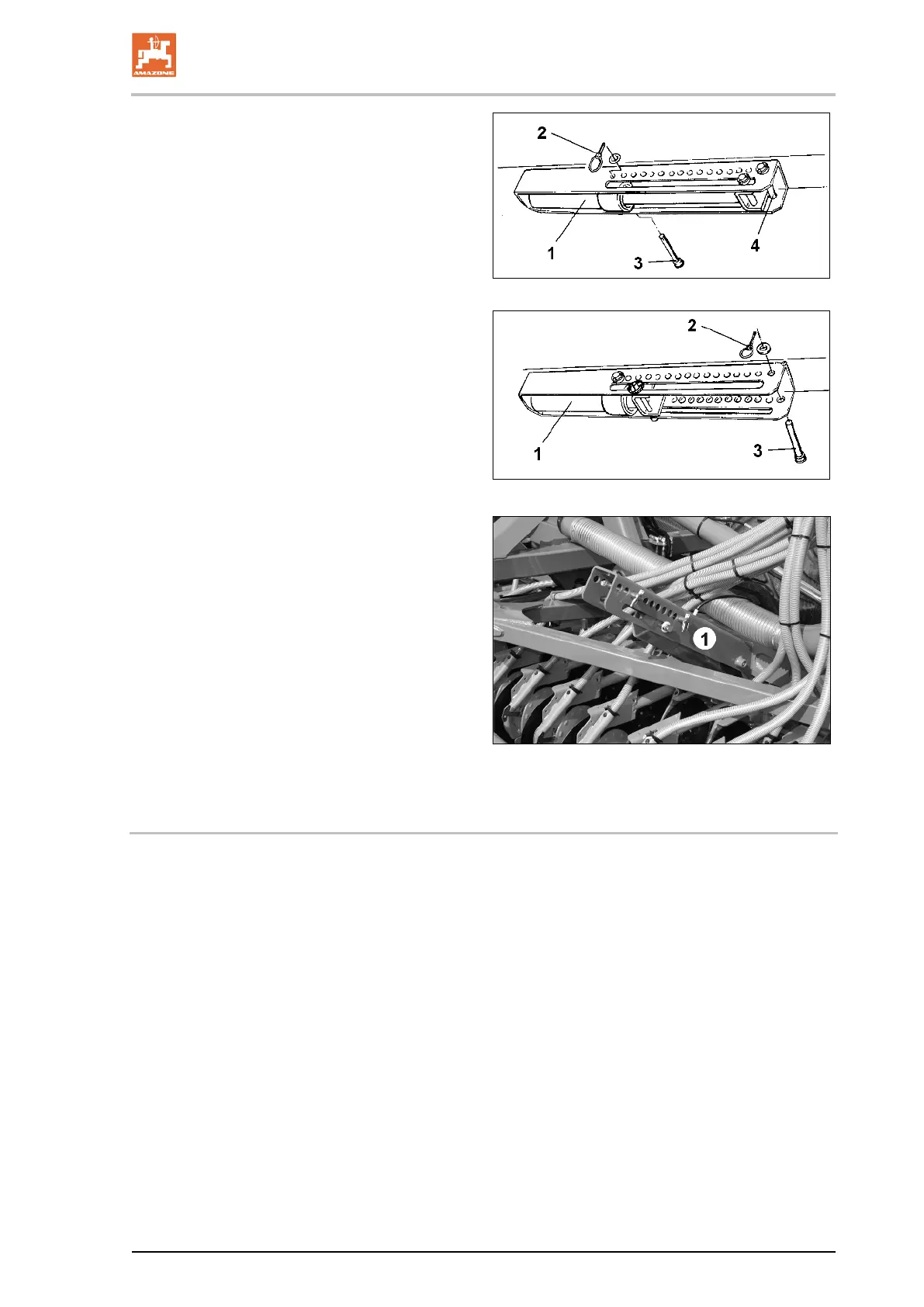
Increasing the coulter pressure
1. Relieve the hydraulic ram (Fig. 82/1) from
pressure .
2. Insert the pin (Fig. 82/3) into one of the
holes of the quadrant plate and secure by
using a clip pin (Fig. 82/2).
Each hole of the quadrant plate is marked with a
figure. An increasing figure indicates an increase
in the coulter pressure (Fig. 83).
81
82
83
8.8 Seed drills with RoTeC
+
coulters
If your seed drill is equipped with RoTeC-(roll
disc) coulters and depth limiters (special option)
and the desired placement depth cannot be
achieved by replacing the pins, all RoTeC depth
limiter discs would have to be re-
according to Seite 92.
The fine tuning then is again conducted by re-
inserting the pins.

 Loading...