EasyManua.ls Logo

American Standard 2A7C3000A - User Manual

American Standard 2A7C3000A
8 pages
Print Icon
To Next Page IconTo Next Page
Loading...
© 2005 American Standard Inc. All Rights Reserved
Since the manufacturer has a policy of continuous product
and product data improvement, it reserves the right to
change design and specifications without notice.
11-AC19D1-1
These instructions do not cover all variations in systems nor
provide for every possible contingency to be met in connec-
tion with installation. All phases of this installation must
comply with NATIONAL, STATE AND LOCAL CODES.
Should further information be desired or should particular prob-
lems arise which are not covered sufficiently for the purchaser’s
purposes, the matter should be referred to your installing dealer
or local distributor.
A. GENERAL
WARNING:
This information is intended
for use by individuals possessing adequate backgrounds of
electrical and mechanical experience. Any attempt to
repair a central air conditioning product may result in
personal injury and or property damage. The manufac-
turer or seller cannot be responsible for the interpretation
of this information, nor can it assume any liability in
connection with its use.
NOTE: AMERICAN STANDARD HAS ALWAYS RECOM-
MENDED INSTALLING AMERICAN STANDARD AP-
PROVED MATCHED INDOOR AND OUTDOOR SYSTEMS.
THE BENEFITS OF INSTALLING APPROVED MATCHED
SYSTEMS ARE MAXIMUM EFFICIENCY, OPTIMUM PER-
FORMANCE AND BEST OVERALL SYSTEM RELIABILITY.
Check for transportation damage after unit is uncrated. Report
promptly, to the carrier, any damage found to the unit.
To determine the electrical power requirements of the unit, refer
to the nameplate of the unit. The electrical power available must
agree with that listed on the nameplate.
B. LOCATION AND PREPARATION OF THE UNIT
1. When removing unit from the pallet, notice the tabs on the
basepan. Remove tabs by cutting with a sharp tool as shown in
Figure 2 (see page 2).
2. The unit should be set on a level support pad at least as large
as the unit base pan, such as a concrete slab. If this is not the
application used please reference ALG-APG0*-EN (*latest revi-
sion number).
3. The support pad must NOT be in direct contact with any
structure. Unit must be positioned a minimum of 12" from any
wall or surrounding shrubbery to insure adequate airflow. Clear-
ance must be provided in front of control box (access panels) & any
other side requiring service access to meet National Electrical
Code. Also, the unit location must be far enough away from any
structure to prevent excess roof run-off water from pouring directly
on the unit. When choosing the location of the unit(s), sound
transmission through air and refrigerant lineset should be taken
into consideration. It is recommended to locate unit(s) away from
areas (bedrooms, etc.) where such sound could be objectionable.
4. The top discharge area must be unrestricted for at least five (5)
feet above the unit.
5. When the outdoor unit is mounted on a roof, be sure the roof will
support the unit’s weight. Properly selected isolation is recom-
mended to prevent transmission to the building structure.
6. The maximum length of refrigerant lines from outdoor to
indoor unit should NOT exceed sixty (60) feet.
7. If outdoor unit is mounted above the air handler, maximum lift
should not exceed sixty (60) feet (suction line). If air handler is
mounted above condensing unit, maximum lift should not exceed
sixty (60) feet (liquid line).
Condensing Units
INSTALLER'S GUIDE
ALL phases of this installation must comply with NATIONAL, STATE AND LOCAL CODES
5 FT. ABOVE UNIT — UNRESTRICTED
1
Models:
2A7C3030-060A3/4000A
IMPORTANT — This Document is customer property and is to remain with this unit. Please return to service information pack
upon completion of work.
Question and Answer IconNeed help?

Do you have a question about the American Standard 2A7C3000A and is the answer not in the manual?

Overview

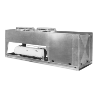
This document describes the American Standard 2A7C3030-060A3/4000A series of outdoor condensing units, which are designed for use with an indoor air handler or furnace to provide cooling for residential and light commercial applications.

Function Description

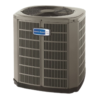
The condensing unit is a key component of a split-system air conditioning or heat pump system. Its primary function is to reject heat from the refrigerant to the outdoor air, thereby cooling the indoor space. When paired with an appropriate indoor coil and air handler, these units provide efficient cooling. The variable speed models offer enhanced comfort and energy efficiency by adjusting their operation to match the cooling demand.

Important Technical Specifications

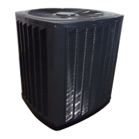
The models covered are 2A7C3030-060A3 and 2A7C3042-060A3, among others in the 2A7C30 series. These units are designed for outdoor installation.

Refrigerant: The units use R-410A refrigerant. Electrical Supply: The electrical supply requirements vary by model, but generally fall within the 24V AC range for control circuits and higher voltages for the main power supply. For example, 18 AWG wire is specified for 150 ft, 16 AWG for 225 ft, and 14 AWG for 300 ft for the 24V circuit. Dimensions: Refer to the "2A7C3 Outline Drawing" for detailed dimensions. For instance, the 2A7C3030A model has a base width of 829 (32-3/4 inches) and a height of 756 (29-3/4 inches). The top discharge area should be unobstructed for at least five feet above the unit. Sound Levels: The units are designed to operate quietly. The location of the unit, especially its proximity to sound transmission paths like windows or patios, should be considered during installation to minimize noise impact. Subcooling Charging: The manual provides detailed tables for subcooling charging based on outdoor liquid temperature and total refrigerant line length. For example, at 80°F outdoor liquid temperature and 10 feet of total refrigerant line length, the liquid pressure should be 163 psi.

Usage Features

Installation:

  • Location: The unit must be installed outdoors on a level, firm pad, at least 12 inches from any wall or surrounding shrubbery to ensure adequate airflow. The top discharge area requires at least 5 feet of unobstructed space above the unit. For optimal sound performance, avoid placing the unit directly under windows or near patios.
  • Mounting: The mounting hole locations are provided in the "Mounting Hole Location" diagram.
  • Refrigerant Lines: The liquid and gas line service valves are equipped with pressure tap ports for easy charging and maintenance. The manual specifies the correct procedures for connecting refrigerant lines, including brazing techniques and pressure testing.
  • Electrical Connections: All wiring must comply with NATIONAL, STATE, AND LOCAL CODES. The unit requires a separate disconnect switch at the outdoor unit.
  • Thermostat: The unit is compatible with the BAYSTAT250B outdoor thermostat, which is described in the wiring diagram.

Operation:

  • Defrost Control: The unit includes a defrost control system that monitors outdoor ambient temperature and coil temperature to prevent ice buildup on the outdoor coil during heating operation (if applicable).
  • Compressor Start-up: The manual outlines the sequence for compressor start-up, including the initial 60-second delay to prevent short cycling.

Maintenance Features

Leak Check:

  • Importance: Regular leak checks are crucial for maintaining system efficiency. The manual recommends using soap bubbles or other leak-checking methods to identify leaks in the refrigerant system.
  • Procedure: After brazing operations, the refrigerant lines must be pressure tested with dry nitrogen to 350-375 psi.

Refrigerant Charging:

  • Procedure: The manual provides detailed instructions for charging the unit, emphasizing the use of the subcooling method. It includes tables to determine the correct subcooling values based on outdoor liquid temperature and total refrigerant line length.
  • Warning: Overcharging or undercharging can lead to reduced performance and potential compressor damage.

Service Valves:

  • Function: The liquid and gas line service valves are designed for easy access to the refrigerant system for charging, evacuation, and pressure testing.
  • Operation: The manual describes how to open and close these valves using a 1/4" square drive wrench.

Troubleshooting:

  • Troubleshooting Chart: A comprehensive troubleshooting chart is provided to help diagnose common system faults, including issues with refrigerant circuits, electrical components, and compressor operation.
  • Error Codes: The unit's control board may flash LED codes to indicate specific faults, aiding in diagnosis. For example, a rapidly flashing LED indicates a normal operation mode, while a slowly flashing LED indicates a fault.
  • Pin Identification (PIN ID): The control board includes a PIN ID feature that can help diagnose issues by indicating which pins are active or inactive.

General Maintenance:

  • Cleaning: The outdoor coil should be kept clean to ensure optimal airflow and heat transfer.
  • Insulation: All refrigerant lines should be properly insulated to prevent energy loss.
  • Wiring: All electrical connections should be checked periodically for tightness and corrosion.

Important Notes:

  • Always refer to the latest revision of the manual for the most up-to-date information.
  • Only qualified personnel should perform installation and service procedures.
  • The manufacturer reserves the right to discontinue, or change at any time, specifications or designs without notice and without incurring obligations.

American Standard 2A7C3000A Specifications

General IconGeneral
BrandAmerican Standard
Model2A7C3000A
CategoryHeat Pump
LanguageEnglish

Related product manuals