EasyManua.ls Logo

American Standard Schlage Link AZEMT500BB32MAA User Manual

American Standard Schlage Link AZEMT500BB32MAA
28 pages
To Next Page IconTo Next Page
Page #1 background imageLoading...
Page #1 background image
The AZEMT500B Thermostat is compatible with single and multistage forced air systems,
including:
• Gas furnace systems
• Oil furnace systems
• Electric furnace systems
• Heat pump systems
• Air conditioning cooling systems
The AZEMT500B Thermostat may be compatible with some other system types, including:
• Boiler systems
• Geothermal systems
• Multi-zoned systems
The AZEMT500B Thermostat is not compatible with the following system types:
• Radiant floor systems
• Wall heating systems
• Proprietary HVAC Communication Protocols
• 240 V Electric baseboard heating systems
Schlage LiNK™
Customer Service:
(877) 288-7707
Contents
Physical Installation and Wiring .......................................................................................................................................2
Field Wiring Diagrams .....................................................................................................................................................4
Enhanced Dehumidification Mode ...................................................................................................................................7
Optional Remote Temperature Sensors Installation ........................................................................................................ 8
System Settings at Thermostat ......................................................................................................................................10
Perform System Checkout .............................................................................................................................................12
Enroll Thermostat into Schlage LiNK™ System .............................................................................................................13
Product Specifications ...................................................................................................................................................14
Operation .......................................................................................................................................................................15
Menu Maps ....................................................................................................................................................................16
User Settings .................................................................................................................................................................18
Installer Settings ............................................................................................................................................................22
Dehumidification Options Settings .................................................................................................................................24
Dual Fuel Settings ..........................................................................................................................................................24
Schedules ......................................................................................................................................................................25
Limited Warranty ............................................................................................................................................................27
Î NOTE: A 24 Volt common and hot wire MUST be connected to the
AZEMT500B for operation.
Î The AZEMT500B Thermostat is compatible with dual fuel systems
(gas or oil furnace & heat pump combined) without adding a dual fuel
accessory relay kit.
Thermostat
Installation and User Instructions
Models AZEMT500BB32MAA
11-HD10D1-2
Question and Answer IconNeed help?

Do you have a question about the American Standard Schlage Link AZEMT500BB32MAA and is the answer not in the manual?

American Standard Schlage Link AZEMT500BB32MAA Specifications

General IconGeneral
Product NameSchlage Link Thermostat
Model NumberAZEMT500BB32MAA
BrandAmerican Standard
CategoryThermostat
ConnectivityZ-Wave
ColorWhite
DisplayLCD
Power SourceBattery powered
CompatibilityZ-Wave enabled systems

Summary

Thermostat Introduction and System Compatibility

System Compatibility Overview

Lists compatible and incompatible HVAC system types for the AZEMT500B Thermostat.

Customer Service Information

Contact details for Schlage LINK Thermostat customer support.

Physical Installation and Wiring Safety

Voltage Hazard Warning

Alerts to electrical shock risk during installation and advises disconnecting power.

Mercury Disposal Notice

Instructions for safely disposing of old mercury-containing thermostat controls.

Physical Installation Steps

Removing and Mounting Thermostat

Steps for detaching the old unit, preparing the wall, and installing the new thermostat.

Field Wiring Diagrams - System Type A

Wiring Table and System Type A

Guide for matching HVAC systems to wiring diagrams and diagram for System Type A.

Remote Sensor Wiring Notes

Details and notes on connecting remote temperature sensors to the thermostat.

Field Wiring Diagrams - System Types B & C

System Type B Wiring Diagram

Diagram for 2 Stage Variable Speed Gas Furnace/Air Handler with 2 Step Cooling.

System Type C Wiring Diagram

Diagram for Heat Pump systems with Air Handler or Gas Furnace.

Field Wiring Diagrams - System Types D & E

System Type D Wiring Diagram

Diagram for 2 Step Heat Pump with Variable Speed Air Handler or Furnace.

System Type E Wiring Diagram

Diagram for Oil Furnace with 1 or 2 Stage Cooling or Heat Pump.

Field Wiring Diagram - System Type F & Dehumidification

System Type F Wiring Diagram

Diagram for 2 Step Cooling/Heat Pump with Variable Speed Oil Furnace.

Enhanced Dehumidification Mode

How enhanced dehumidification works with variable speed systems.

Optional Remote Temperature Sensors

Sensor Installation Guide

Wiring specs, placement, and interference precautions for remote sensors.

Remote Sensor Configurations

Connection and operation for various sensor setups (Indoor, Outdoor, Averaging).

Final Thermostat Installation Steps

JP1 Jumper & Thermostat Face Attachment

Instructions for modifying the JP1 jumper and securing the thermostat faceplate.

System Power-Up

Turning on the heating and cooling system after installation is complete.

Thermostat Settings - Time and System Checkout

Setting Time and Date

Navigating menus to configure the thermostat's clock and calendar.

System Checkout Guidance

Directs users to specific checkout steps based on their HVAC system type.

Mechanical Settings Configuration

Gas, Electric, and Heat Pump Settings

Configuring system type, stages, fan type, and dual fuel settings.

System Checkout and Sensor Configuration

Perform System Checkout

Testing all operational modes including Fan, Heating, and Cooling.

Configure RS2 for Outdoor Sensor

Optional step to set the RS2 input for outdoor temperature sensing.

Schlage LiNK System Enrollment

Bridge Preparation and Thermostat Enrollment

Steps to prepare the Z-Wave bridge and enroll the thermostat into the LiNK system.

Verify Enrollment Status

Checking the ZNID to confirm successful thermostat connection to the bridge.

Online Control and Product Specifications

Establish Online Control

Steps to link the thermostat to a Schlage LiNK account for remote access.

Exclusion Process

Instructions on how to unenroll a thermostat from the Z-Wave bridge.

Product Specifications

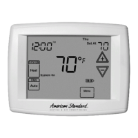
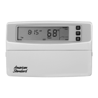
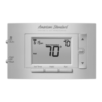
Technical details and features of the AZEMT500BB32MAA thermostat model.

Thermostat Operation Overview

Thermostat Display Elements

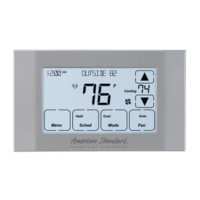
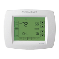
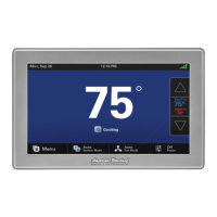
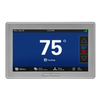
Description of screen components like Clock, Temperature, and Setpoint displays.

Button Functionality

Explains the purpose of Menu, Mode, Fan, and Schedule buttons.

User Settings Menu Navigation

Minimized Display Mode

Setting the thermostat screen to show only the current temperature.

User Settings Menu Map

Visual guide to navigating the various options within User Settings.

Installer Settings Menu Navigation

Accessing Installer Settings

Procedure for entering the hidden installer configuration menu.

Installer Settings Categories

Overview of the different configuration sections available to installers.

User Settings - Filter Service

Filter Service Function

Explains runtime tracking and filter replacement reminders.

Managing Filter Service

Options to view, reset, change interval, or disable the filter service feature.

User Settings - Maintenance, Display & Environment

Maintenance Service Function

Tracks accumulated runtime for maintenance reminders.

Screen Timeout & Minimized Display

Controls screen auto-off behavior and minimized display settings.

RH% Setpoint & Balance Point

Configurable settings for dehumidification and dual fuel operation modes.

User Settings - Temperature & Usage Graphs

F/C Settings

Allows selection between Fahrenheit or Celsius temperature display.

Internal Sensor Calibration

Adjusts the reading of the internal temperature sensor by +/- 7 degrees.

Usage Graph

Displays daily heating and cooling runtime history for the past week.

User Settings - Backlight & ESM

Backlite/Display Settings

Adjusts backlight timeout duration and screen contrast level.

Adjust ESM Setpoints

Configures temperature setpoints for the Energy Saving Mode (ESM).

Installer Settings - Core Configurations

Installer Settings Overview

Access and editing of advanced configuration options for qualified installers.

Display Lock & System Settings

Controls button lockout and system-wide parameters like max/min setpoints.

Time Delays & Sensor Settings

Configures minimum run/off times, T-Sense, and remote sensor settings.

Fan Features & Defaults

Settings for fan cycler, fan times, and restoring factory defaults.

Installer Settings - System Parameters

Balance Point & Schedule Enable

Configures dual fuel lockout temp and enables thermostat scheduler.

Recovery Enable & H/C Delta

Manages system recovery for schedules and setpoint separation (delta).

Heating Delta Settings

Adjusts heat start/stop differentials for stages and auxiliary heat.

Cooling Delta Settings

Adjusts cooling start/stop differentials for stages.

Installer Settings - Mechanical & Dehumidification

Mechanical Settings - Gas/Electric

Configures system type, fan type, and stage settings for Gas/Electric systems.

Mechanical Settings - Heat Pump

Configures system type, changeover, stages, and auxiliary heat for Heat Pumps.

Mechanical Settings - Dual Fuel

Configures dual fuel system type, restricted mode, and balance point.

Dehumidification Options

Settings for cooling droop, smart fan, and RH calibration.

Schedules Management

Schedules Overview

Explains schedule control methods (Z-Wave vs. thermostat) and structure.

Enable/Disable Schedules Menu

Activates or deactivates the thermostat's scheduling features.

Load Preset Schedules

Options to load pre-defined Comfort or Energy Save schedules.

Advanced Schedule and Fan Control

View and Set Heat/Cool Schedules

Customizing daily heating and cooling setpoints for different time periods.

Copy Day Schedule

Duplicates a day's schedule to other days of the week.

Smart Continuous Fan (SCF) Operation

Utilizing continuous fan operation for humidity control based on RH setpoint.

Limited Warranty Information

Warranty Coverage and Exclusions

Details on warranty period, coverage, and specific exclusions for the thermostat.

Liability Limitations

Legal disclaimers regarding implied warranties and consequential damages.

Regulatory Compliance Notices

FCC Compliance Statement

FCC rules regarding radio frequency interference for digital devices.

Industry Canada (IC) Notice

Compliance with Canadian radio interference regulations for license-exempt devices.

Related product manuals