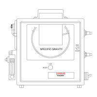
The Chandler Engineering Model 3330 Inline Viscometer is a low-pressure Couette (cup/bob) viscometer designed for real-time measurement of oilfield fluids during treatments. It connects directly into a sample line from the clean fluid delivery line, allowing for continuous monitoring of fluid viscosity.
Function Description:
The viscometer operates by measuring viscosity at a standard shear rate of 511 sec⁻¹ using the API standard R1 rotor, B1 bob, and F1 spring. The F1 spring is specifically calibrated to provide 1 degree of rotation per 1 centipoise of viscosity. Clean fluid flows into the instrument, where a specially designed rotor (cup) pulls the fluid into the gap between the rotor and the bob as the rotor turns. This unique design allows for continuous measurement at a constant sample rate, making it insensitive to the flow rate through the instrument. The fluid in the gap is sheared, which produces a torque on the bob. This torque is then transmitted to a resisting spring via a magnetic drive. The magnetic drive serves a dual purpose: it mechanically supports the bob and transmits torque without the need for shaft seals, thus reducing potential leak points and maintenance. The bob's rotation, which is proportional to the fluid's viscosity, is measured by a high-precision encoder. The encoder signal is then scaled to provide a direct viscosity reading. An optional pH measurement system is also available for comprehensive fluid analysis.
Important Technical Specifications:
- Pressure Range: 100 PSIG
- Temperature Range: 32°F - 160°F
- Flowrate: 1-5 gpm
- Viscosity Range: 0-160 cP
- Input Voltage: 12VDC
- Power: 6 A @ 12VDC
- Dimensions: 13.5" x 17" x 20"
- Net Weight: 56 lbs. (36 kg)
- Operating Speed: 300 RPM (511 sec⁻¹)
- Connections: 1½" NPT threads
- Signal Output:
- Viscosity: 4-20 mA @ 600 ohms max (self-powered, single-ended current source, calibrated for 4mA = 0 cP and 20mA = 160 cP). Users are warned not to connect this signal to a circuit that provides power over the current loop, as the transmitter provides its own power.
- Temperature: 4-20 mA @ 600 ohms max (DC loop powered, calibrated for 4mA = 0°C and 20mA = 70°C).
- Environmental Rating: Meets IP67 for outdoor environments.
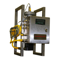
Usage Features:
The Model 3330 Inline Viscometer is designed for ease of use, from setup to operation. It can be configured for either portable or permanent installation. The electronics enclosure includes a 6-foot instrument cable for remote mounting of the operator interface, offering flexibility in placement. Fluid connections are made via two ½" NPT threads. It's recommended to connect the fluid delivery line from a clean fluid pressure source (e.g., a clean side blender centrifugal) to the lower viscometer port, and the return line from the upper port to a return gel tank or the suction side of the clean side centrifugal. A coarse screen should be placed at the inlet to prevent large particles from entering the viscometer. The instrument requires a 12 VDC power supply, with a bare wire lead cable provided for wiring. The power cable connections are GRN/YEL (Chassis Ground), Brown (0 VDC), and Blue (12 VDC). Turning on the instrument automatically zeros the encoder, requiring the fluid input valve to be closed and no fluid flowing through the instrument at that time. A green LED indicates power is on, while a red LED indicates a motor controller fault.
Maintenance Features:
The viscometer is designed for infrequent and easy maintenance, typically only required if performance issues like large errors, hysteresis, or offsets are observed.
- Cleaning: Regular hand cleaning is recommended after each use to remove fluid contamination. This involves draining the fluid, disconnecting the encoder cable, unthreading the large coupling nut to remove the measurement head, carefully wiping the inside of the viscometer and bob dry, and flushing the vessel and rotor. The bob assembly is magnetically held and can be removed by unthreading a retaining nut. Caution is advised to keep the bob assembly away from magnetic materials due to strong internal magnets.
- Calibration: Calibration should be checked before every use with a known clean calibration fluid (e.g., 100cP calibration oil). The process involves filling the viscometer with calibration fluid, connecting to power, turning on the motor, and checking the viscosity reading against the known value (should be within 2cP). Adjusting calibration involves loosening set screws on the spring mandrel, turning the mandrel clockwise to decrease viscosity or counterclockwise to increase it, then re-tightening the screws. The spring assembly may need manual adjustment to position the encoder against the zero stop. Power cycling is required to zero the encoder after adjustment.
- Torsion Spring Assembly Replacement: The viscometer uses a standard F1 spring. Replacement involves unthreading the top cap, loosening set screws on the brass spring clamp, removing screws from the spring housing, and then loosening set screws on the top row of the spring holder to remove the spring. Installation of a new spring is followed by reassembly and recalibration.
- Encoder Assembly Replacement: This involves removing screws from the top of the measurement head, carefully detaching the encoder/spring assembly (sealed with an O-ring), removing screws holding the encoder reader, and then removing the mag drive from the bearings. Bearings should be checked for friction and replaced if necessary. Bearings must be kept clean, dry, and away from magnets to prevent magnetization. The encoder can be removed from the mag drive shaft by loosening two screws. Reassembly is followed by recalibration.
- Rotor Assembly Replacement (Seal/Bearings): This involves unthreading the large coupling nut for the motor, removing two screws attaching the rotor to the shaft, and removing screws holding the motor flange to the bearing housing. The bearing retainer is unthreaded to remove the shaft and bearing assembly, and the shaft seal is removed. Bearings and seals are inspected and replaced as needed, followed by reassembly.
- Bob Assembly Replacement (Shaft Bearings): The bob shaft uses two glass journal bearings. After carefully removing the measurement head and the bob assembly (which is magnetically held), the set screw on the bob is loosened to remove the bob from the shaft. The retainer is slid off, and the threaded ring is removed to push out the glass bearing. Bearings are inspected and replaced as needed. Reassembly of the instrument is then performed.
- Maintenance Schedule: A schedule is provided as an initial guide, with frequencies for cleaning (each test), calibration (check each test, calibrate as required monthly), and replacement of rotary seals, O-rings, encoder bearings, rotor bearings, and thermocouples (as needed, 6 months, or annually).