Figure 2-3, Main Menu 1
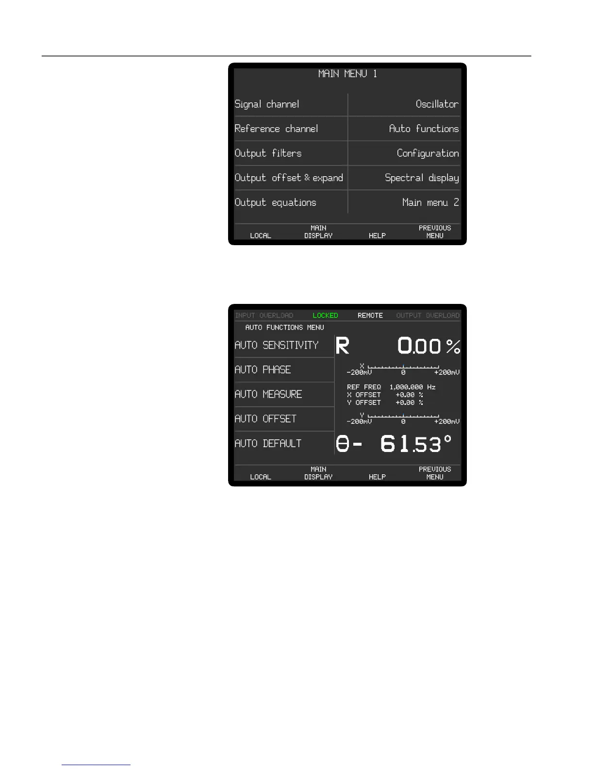
6) Press one of the keys adjacent to the Auto functions menu item to enter the Auto
Functions menu, shown below in figure 2-4.
Figure 2-4, Auto Functions Menu
7) Press one of the keys adjacent to the Auto Default menu item. This will set all of
the instrument's controls and the display to a defined state. The display will
revert to the Main Display, as shown below in figure 2-5, with the right-hand
side showing the vector magnitude, R, and the phase angle, , of the measured
signal in digital form, with two bar-graphs showing the X channel output and Y
channel output expressed in millivolts. The left-hand side shows five instrument
controls, these being the AC Gain in decibels, full-scale sensitivity, output time
constant, reference phase and internal oscillator frequency. The resulting
dynamic reserve (DR), in decibels, is also shown.
 Loading...