122770 06 18-09-2007 49
ATC-125/140/155/156/157 A/B
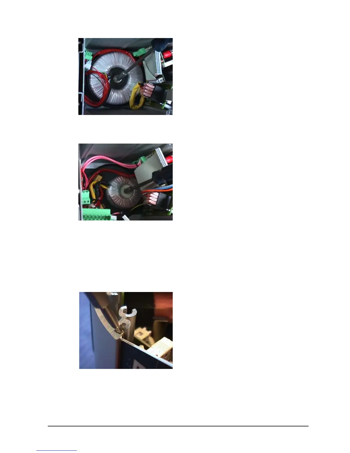
Remove the M6 nut and washer
with a 10-mm socket wrench. Cut
the straps holding together the
wires and retract the transformer
after having disconnected the wires
to the power-inlet module. Note the
position of the straps for later
assembly.
ATC-250/320/650 A/B
Remove the M4 nut and washer
with a 7-mm socket wrench. Cut
the straps holding together the
wires and retract the transformer
after having disconnected the wires
to the power-inlet module. Note the
position of the straps for later
assembly.
I. Removal of I/O Plates, all Models
(Exploded views, pos. 3a + 3b)
First follow steps A through D followed by retraction of the
two aluminium plates as described in the guidelines above.
The I/O plates are identically
secured in all calibrator types:
From above remove the two Allen
screws with a 2mm Allen key.

 Loading...


