50 18-09-2007 122770 06
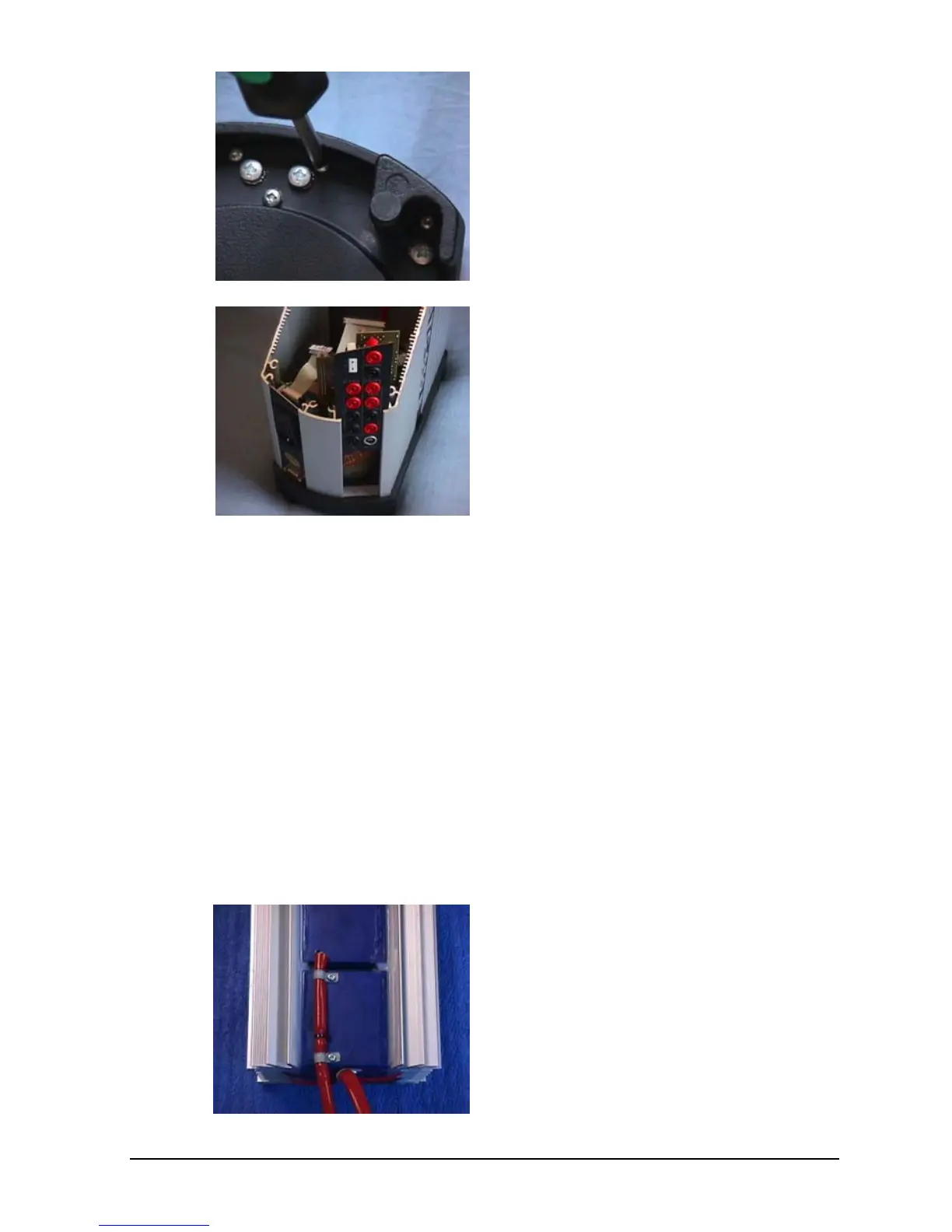
From beneath: Remove the 2
screws.
Retract the I/O plate after
disconnecting all wires. This picture
shows the input plate for an ATC-
650 B calibrator.
J. Replacement of Reference Sensor
(Exploded views, pos. 4)
To replace the reference sensor in the well unit, follow steps
A through D followed by step F and then follow the
procedure given below.
For the ATC-125/140/155/156/157 A/B the hole for the
reference sensor will be filled with compound and the well
unit must be heated up to 100 – 150°C in order to soften the
compound and thereby avoid breaking the sensor when
removing it.
ATC-155 A/B:
Place the well unit with the
reference sensor towards you.

 Loading...


