122770 06 18-09-2007 51
Remove the 2 screws and retract
the reference sensor from the Well
Unit.
When remounting a new sensor, it
must be placed in the hole together
with 0.2ml compound.
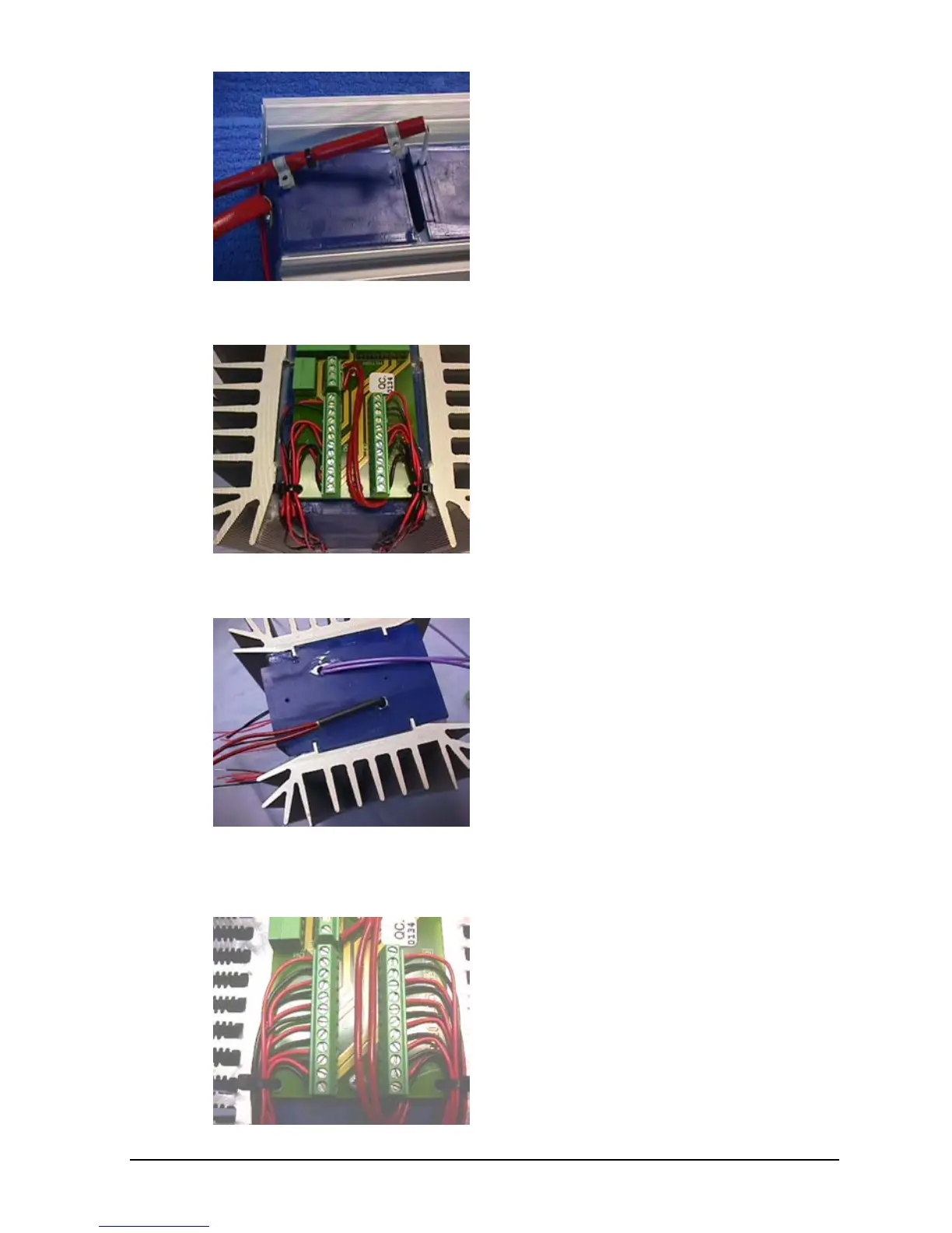
ATC-156 A/B:
Place the well unit upside down
and remove the 2 screws from the
Connection PCB.
Carefully lift up the Connection
PCB and retract the reference
sensor from the well unit.
When remounting a new sensor, it
must be placed in the hole together
with 0.3ml compound.
The reference sensor is the one
placed in the right hole beneath in
the picture.
Disconnect the 2 sensor wires from
the Connection PCB.
ATC-157 A/B:
Place the Well Unit upside down
and remove the 2 screws from the
Connection PCB.
Carefully lift up the Connection
PCB and retract the reference
sensor from the well unit.

 Loading...


