EasyManuals Logo

Ametek JOFRA ATC-125 A Service Manual

Ametek JOFRA ATC-125 A
89 pages
To Next Page IconTo Next Page
To Previous Page IconTo Previous Page
Page #57 background imageLoading...
Page #57 background image
122770 06 18-09-2007 57
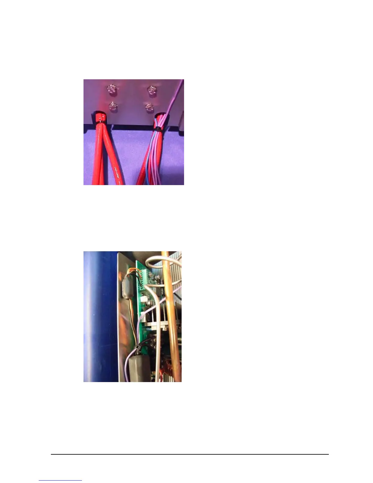
The other end is bend 25mm from
the tip of the sensor and placed in
the sensor hole on top of the well.
After reinstalling both ends of the
sensor in the well, the wires must
be strapped together.
When a new sensor has been
installed, a new gasket has to be
installed on top of the well. The
new gasket is supplied with the
sensor kit.
L. Replacement of Stirling Control PCB FPSC
(Exploded view – fig. 3.2, pos. 22)
ATC-125 A/B only:
Remove the 4 nuts holding the
PCB.
Carefully pull out the PCB.

Other manuals for Ametek JOFRA ATC-125 A

Questions and Answers:

Question and Answer IconNeed help?

Do you have a question about the Ametek JOFRA ATC-125 A and is the answer not in the manual?

Ametek JOFRA ATC-125 A Specifications

General IconGeneral
BrandAmetek
ModelJOFRA ATC-125 A
CategoryMeasuring Instruments
LanguageEnglish

Related product manuals