M O D E L 2 1
O P E R A T
I O N M A N U A L
13
1313
13
5.3 ROTOR AND PARTS REPLACEMENT
ROTOR AND
PARTS REPLACEMENTROTOR AND PARTS REPLACEMENT
ROTOR AND PARTS REPLACEMENT
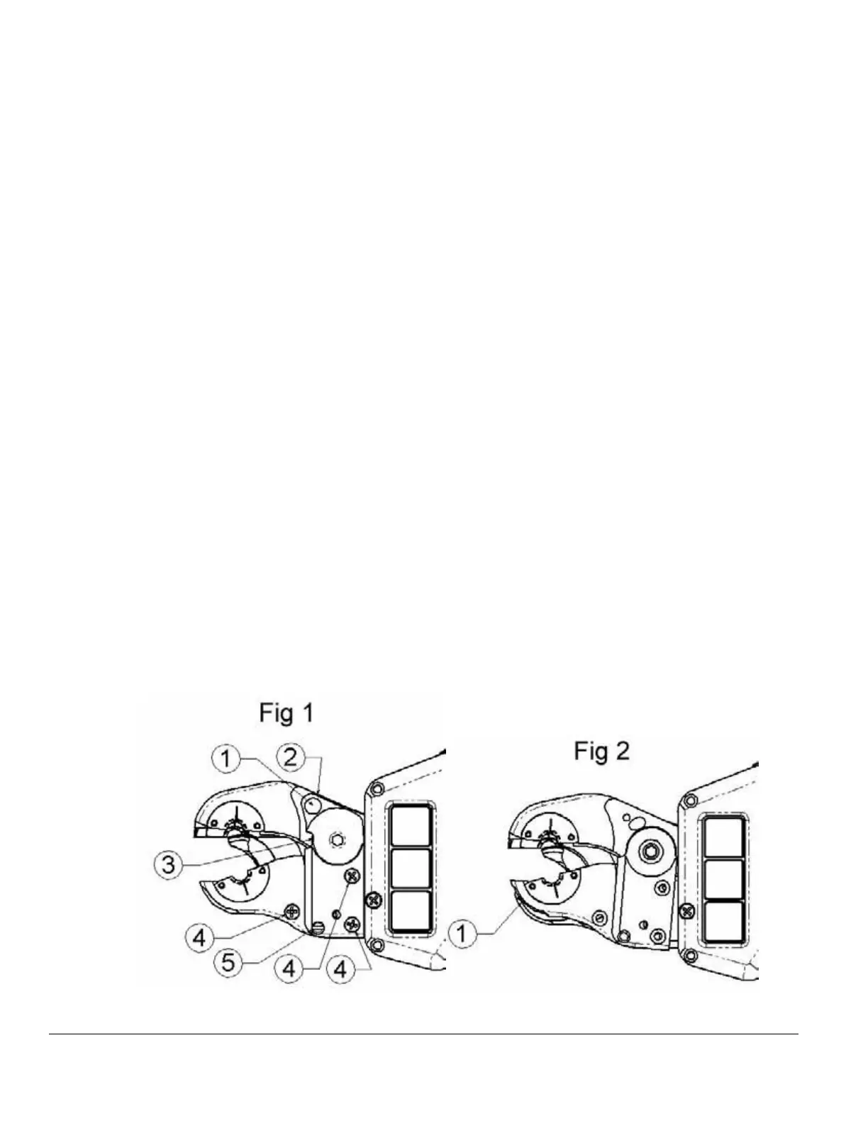
1. With the jaws in the open position turn off the power to the Controller.
2. Remove the Torsion cap retaining screw (Fig 1 Item 1).
3. Relieve spring pressure on the torsion cap by loosening the torsion tension set
screw (Fig 1 Item 2).
4. Lift torsion cap off of weld head. If necessary, gently pry between the torsion cap
and top jaw #2 (Fig 1 Item 3).
5. Remove the three Phillips screws (Fig 1 Item 4).
6. Remove the jaw alignment shoulder bolt (Fig 1 Item 5).
7. Rotate bottom jaw #2 clockwise to clear the interlock with bottom jaw #1(Fig 2
Item 1).
8. Lift bottom jaw #2 off of the weld head.
9. Gently lift the stationary insulator out of the weld head (Fig 3 Item 1). Lift the
contact strip (Fig 4 Item 1) out of weld head. Gently lift the rotor assembly (Fig 4
Item 2) out of the weld head (rock rotor if necessary).
10. Inspect all components for wear and damage and replace as necessary.
11. Install the rotor verifying that the bottom edge of the gear is flush with the race
(Fig 4 Item 3).
12. Install the contact strip by pressing the opening on the contact strip onto the boss
of the power lug (Fig 4 Item 4).
13. Install the stationary insulator and verify that it is flush with bottom jaw #1 (Fig 3
Item 2).
14. Install bottom jaw #2, torsion cap and remaining hardware.