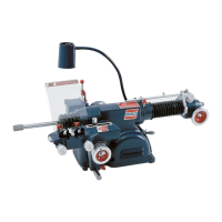
AMMCO Drum & Disc Brake Lathes • 5
cross feed speed is adjustable on the 4000, 4100, and
7500:
1. Using the 3-position lever, select Fine (0.002”
[0.05 mm]) or Coarse (0.010” [0.25 mm]). The Neutral
position is the off position (no movement). The cross
feed may also be operated manually.
V-Belt Tension and Adjustment
A loose belt can cause slippage when taking heavy
cuts. A belt that is too tight can cause vibration and
possible sub-standard finishes on machined drums and
rotors. Check and adjust belt monthly.
There should be between
1
4” to
1
2” of play in the belt.
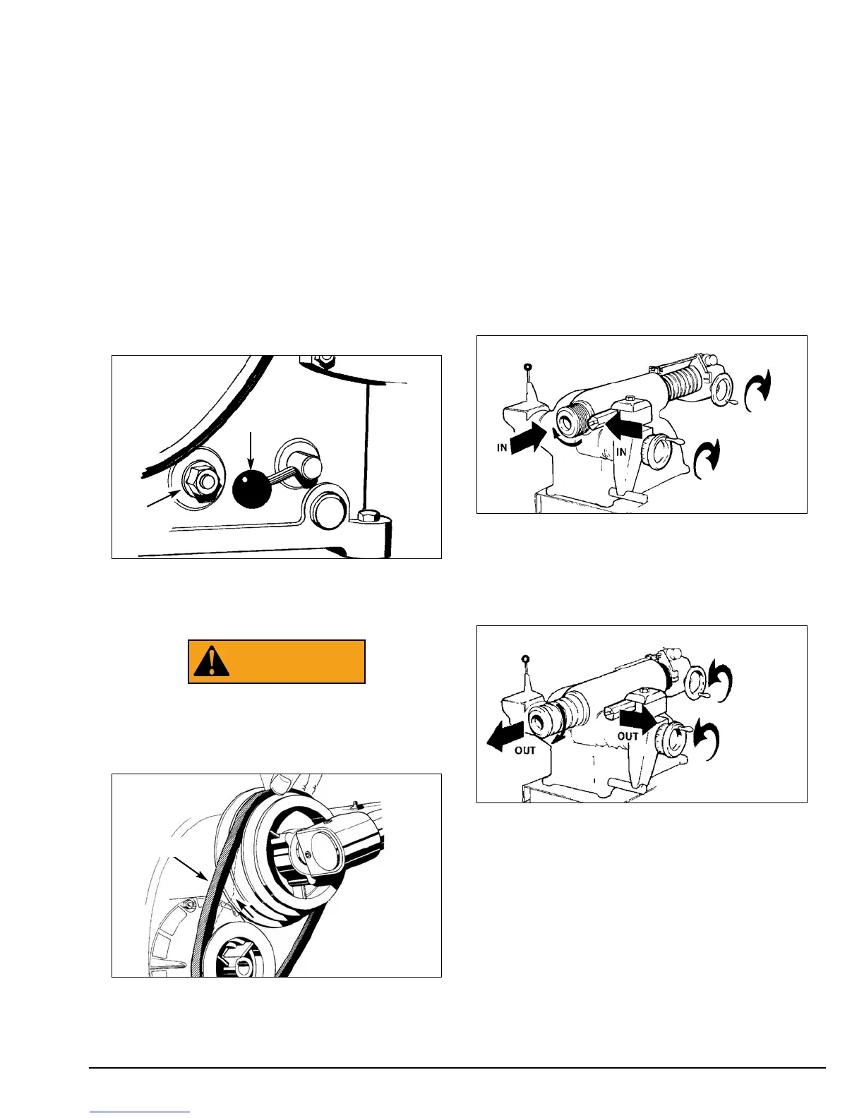
1. Position the v-belt speed adjusting lever to the left
(counterclockwise) to the fully engaged position.
2. Loosen the adjustment nut.
Figure 5 – Engage lever and loosen nut
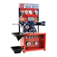
3. Push in on the belt approximately 14” to 12”
(0.64 to 12.7 mm) and hold.
Hazard Areas must be protected during lathe opera-
tion. Keep shields and guards in place. Keep fingers
out of these areas and away from rotating parts.
4. Retighten the adjusting nut.
Figure 6 – Press the belt in and tighten adjusting nut
Poly V-Belt Tension
For poly v-belt adjustment, use the same procedure
as for the standard v-belt, with these exceptions:
1. The poly v-belt should be adjusted to deflect 332”
with a 5 pound push on the belt. The ideal tension is
the lowest tension at which the belt will not slip under
the highest load.
2. Check and adjust as required the tension during
the first day of operation. Do not overtighten.
Basic Operation of Handwheels
Clockwise rotation of the spindle feed handwheel
retracts the spindle in towards the lathe.
Clockwise rotation of the cross feed handwheel
moves the cutting tool in towards the lathe.
Figure 7 – Clockwise rotation of handwheels
Counterclockwise rotation of the spindle feed hand-
wheel extends the spindle out away from the lathe.
Counterclockwise rotation of the cross fee hand-
wheel moves the cutting tool out away from the lathe.
Figure 8 – Counterclockwise rotation of handwheels