14
Installation
Revision: 7 – Mar 2014 OMMB00010
Section 5 Installation
WARNING
The valve is heavy, refer to Section 9 (Technical Data). The
appropriate manual handling precautions must be applied to avoid
personnel injury.
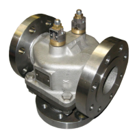
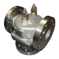
5.1 Installing the valve
5.1.1 Before starting installation
1. Upon receipt, the valve should be checked for damage
sustained in shipping. All AMOT valves have nameplates
attached, which are stamped with the valve model number and
serial number.
2. Understand the intended use of the valve as described in
Section 3.
3. Before installation, ensure that the valve is suitable for the
purpose, checking temperature, pressure and material
parameters, and any special approval requirements. In
particular note that Buna N seals are not suitable for certain
fluids, including phosphate ester and diester oils. With such
oils, nickel plated assemblies should also be specified to
protect the bronze parts. Check that the intended pipe fittings
are suitable for the application.
4. The valve size should have been selected in accordance with
the anticipated flow rate through the valve. To maintain good
temperature regulation the pressure drop across the valve
should be in the 137 to 482 millibar (2 to 7 psi) range.
5. If the valve is to be fitted at a high point in the system, the
system should be vented to prevent trapped air around the
temperature elements.
6. For optimum temperature regulation the system should be
designed so that the element is in the mid-position under
nominal conditions. To achieve this it may be necessary to
balance the fluid flow by inserting an orifice in the by-pass
circuit.
7. If appropriate read and understand the legal requirements of
installing the valve within the European Union as described in
Section 4.
5.1.2 Mounting the Valve in the Pipe
The valve may be mounted in any orientation; but should be properly
supported and not subjected to excessive bending. Ensure the pipe