20
Maintenance
Revision: 7 – Mar 2014 OMMB00010
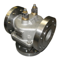
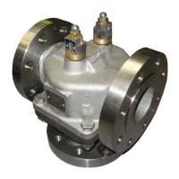
1. Refer to figure 7.1. Remove housing nuts (Item 12) and split valve.
Remove the lower housing (Item 2) taking care not to damage the
elements. Remove and discard housing gasket (Item 9) ensuring
any traces of the gasket are removed from the housing mating
faces. Please note that in some sizes of Model B Valves ‘O’ rings are
used instead of gaskets.
2. If removing element from BO valve (non manual override) simply
pull the element from the upper housing. Go to step 9.
3. If removing element from BR valve (manual override) only
dismantle one at a time to eliminate the chance of the manual
override parts being mixed up.
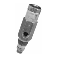
4. Carefully remove the indicator pin (item 36).
5. Remove the locknut (Item 38) from the override stem (Item 21).
6. Remove override housing retaining screws (Item 28).
7. Unscrew override housing from the override stem (Item 21) and set
aside the shims.
8. Pull the element from the upper housing and if changing the
element un-pin the override stem from the element link.
9. Remove ‘O’ rings. BO valve item 7. BR valve item 7 & 17.
10. Inspect valve seat for wear or damage. If required replace valve
seat (Item 3), remove by unscrewing bushing (Item 5). Bushing
A/F 7/8”.
7.2 Assembling the valve
1. Lubricate gasket (Item 9) liberally with a good grade of petroleum
grease, allow to soak.
2. If valve seat changed, refit bushing with Loctite 241 locking
compound.
3. Lightly grease and stretch new ‘O’ ring (Item 7) and fit into upper
housing. Position ‘O’ ring concentrically to assist element assembly.
4. If replacing a BR valve element, then fit override stem (Item 21) to
element link with pin (Item 20).
5. Insert element into the upper housing taking care not to damage the
‘O’ ring.
6. For BO valves go to step 10
7. For BR valves. Lightly grease ‘O’ ring (Item 17) and slide over
override stem and seat into recess in the stem adaptor followed by
the ‘O’ ring retainer (Item 37).
8. Screw manual override housing onto override stem. Refit shims
(Item 24). Ensure indicator plates are facing outward, on 6BR one
row to face nameplate and two rows to face other side. Secure
housing to stem adaptor with screws (Item 28) and Loctite 241. Fit
indicator pin (Item 36) into override stem, ensuring element
assembly still closes.