EasyManua.ls Logo

AMOT B - Model Number Identification System

AMOT B
26 pages
Print Icon
To Next Page IconTo Next Page
To Previous Page IconTo Previous Page
Loading...
6
Use in EU
Revision: 7 Mar 2014 OMMB00010
3.3 Identification of Model Number
Example Code
4
BO
S
J
075
07
-0
-XXX
Code Description
Valve Size
Nominal Bore Size
Number of Elements
1 1/2
1 1/2 inch (DN40)
1
2
2 inch (DN50)
1
2 1/2
2 1/2 inch (DN65)
2
3
3 inch (DN80)
2
33
3 inch (DN80)
3
4
4 inch (DN100)
4
5
5 inch (DN125)
6
6
6 inch (DN150)
9
8
8 inch (DN200)
16
Valve Model
Model
BO
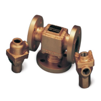
Screwed connections (1 1/2" and 2" only)
BO
Flanged (2 1/2" to 8" only)
BC
Flanged 'T' configuration (1 1/2" and 2" only)
BF
Flanged 'F' configuration (2" only)
BH
Screwed high pressure (1 1/2" and 2" only)
BR
Manual override (2" to 8 only")
BP
Special ST.ST with Manual Override (Refer OMM00144)
BQ
Special ST.ST B Valve (Refer OMM00144)
Valve Material
Valve Material
A
Aluminium (not 8 and 33)
B
Bronze (not 33)
C
Cast Iron*
D
Ductile iron
S
Steel (2", 2 1/2", 3" and 4" only)
R
Stainless steel (2", 2 1/2", 3" and 4" only)
Port Connection
Port Connection
A
Flanged PN6
B
Flanged PN10
C
Flanged PN16
F
Flanged ANSI 125 lb (cast iron, bronze and ductile only)
J
Flanged ANSI 150 lb (steel and stainless steel only)
H
Flanged ANSI 300 lb (steel and stainless steel only)
L
Flanged JIS 10k
P
Flanged JIS 5k
T
Threaded NPT (1 1/2" and 2BO only)
U
Threaded BSP (PL) (1 1/2" and 2BO only)
Control Temperature (°F)
***
See Element Temperatures Table 2
Element Type
Element Type
**
See Element / Seal Types Table 3
Leakhole sizes
Leakhole sizes inches
0
None
A
1/2" Dia
B
1/4" Dia
C
3/8" Dia
D
1/8" Dia
E
1/16" Dia
F
3/32" Dia
G
3/16" Dia
H
5/16" Dia

Related product manuals